4.10.6 CRANE BOOMS
If the crane has a fixed bend or curved boom, it can be setup in two ways.
Either by sending fixed encoder values from the PLC/encoder device or by entering an offset for the
bend in the configuration software.
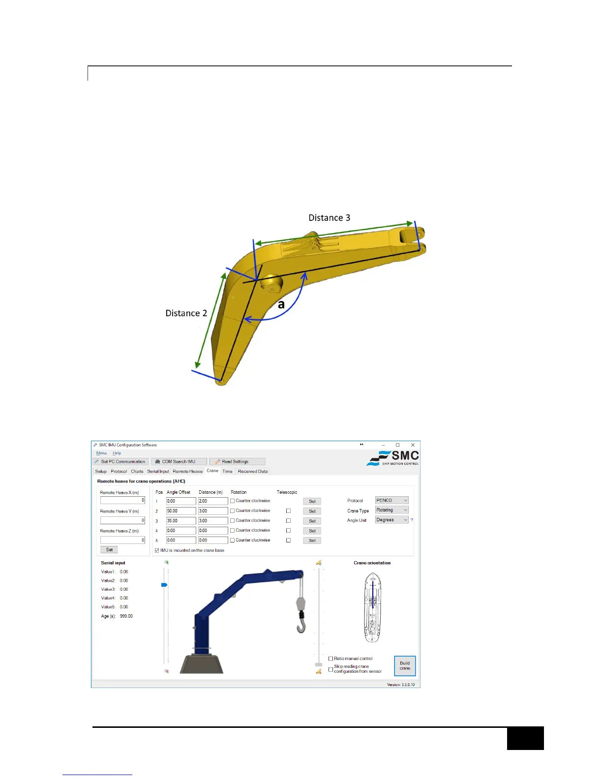
The boom can then be visually represented by dividing the boom into 2 or 3 sections, as appropriate.
In the example below the curved section is divided into two, Distance 2 and Distance 3.
Measured from the knuckle joint to the where the center lines of the arm converge.
The center line convergence point also provides angle (a) used for the Angle Offset.
For example, if Distance 2 is 3m and Distance 3 is 3m with an offset angle (a) of 35 degrees between
them, the crane below will be drawn.
The offset is positive in value, if the crane bend is clockwise/downwards.
 Loading...