3.5 SIDEWAYS MOUNTING
When the Motion sensor is delivered for Sideways mounting the motion sensor cannot be used for
Deck mounting without a recalibration at the factory.
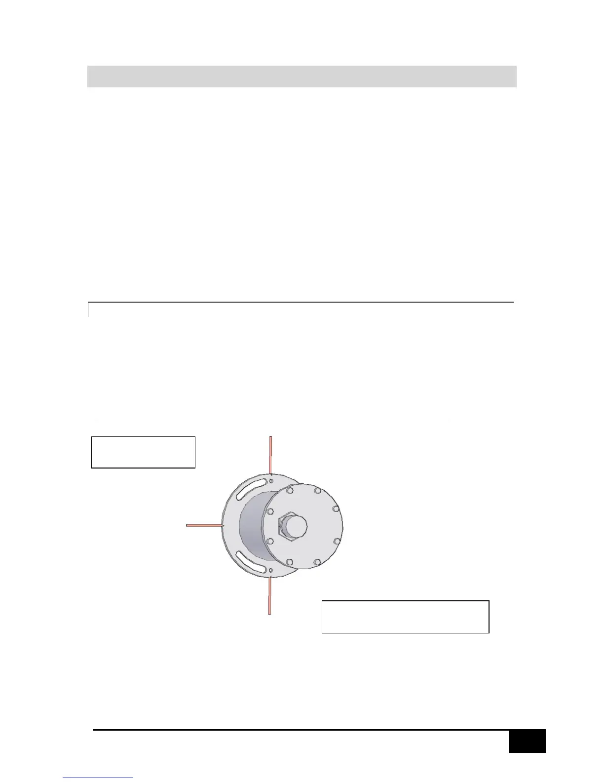
The mounting of the motion sensor must be carried out with the mounting plate oriented vertically.
The notches on the mounting plate mark the orientation points of the motion sensor.
The single notch must be mounted pointing horizontally to the bow/stern/port/starboard of the
vessel.
Depending on the mounting orientation the Motion sensor will need its coordinate system to be
selected in the SMC IMU configuration software Mounting Orientation options.
Note: The Motion sensor cannot be mounted in the sideways orientation unless it has been
specifically calibrated to do so. Contact SMC if clarification is required.
3.5.1 TOP OF THE MOTION SENSOR POINTING TO THE BOW
When the Motion sensor top, where the connector is located, is pointing to the Bow of the vessel the
single notch must be pointing horizontally to Starboard.
In the SMC IMU Configuration Software IMU top to the Bow must be selected.
 Loading...