- 65 -
No.SFOD-OMT0010-B
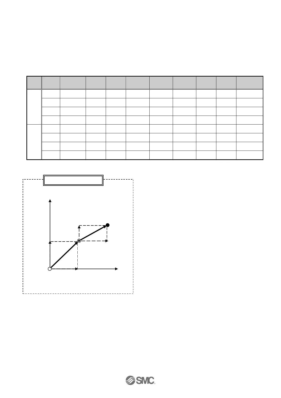
Example) After a Return to origin, move from the origin position at 100mm/s of composite speed to a
point at100mm on Axis 1 and 100mm on Axis 2 (Step No.1).
Then, move from the current position at 50mm/s of composite speed to a point at 100mm on Axis
1 and 50mm on Axis 2 (Step No.2).
Step Data Setting Examples

 Loading...


