- 9 -
2.4 Start up procedure
Install, wire, set and operate the controller referring to the procedure below when the product is used
for the first time.
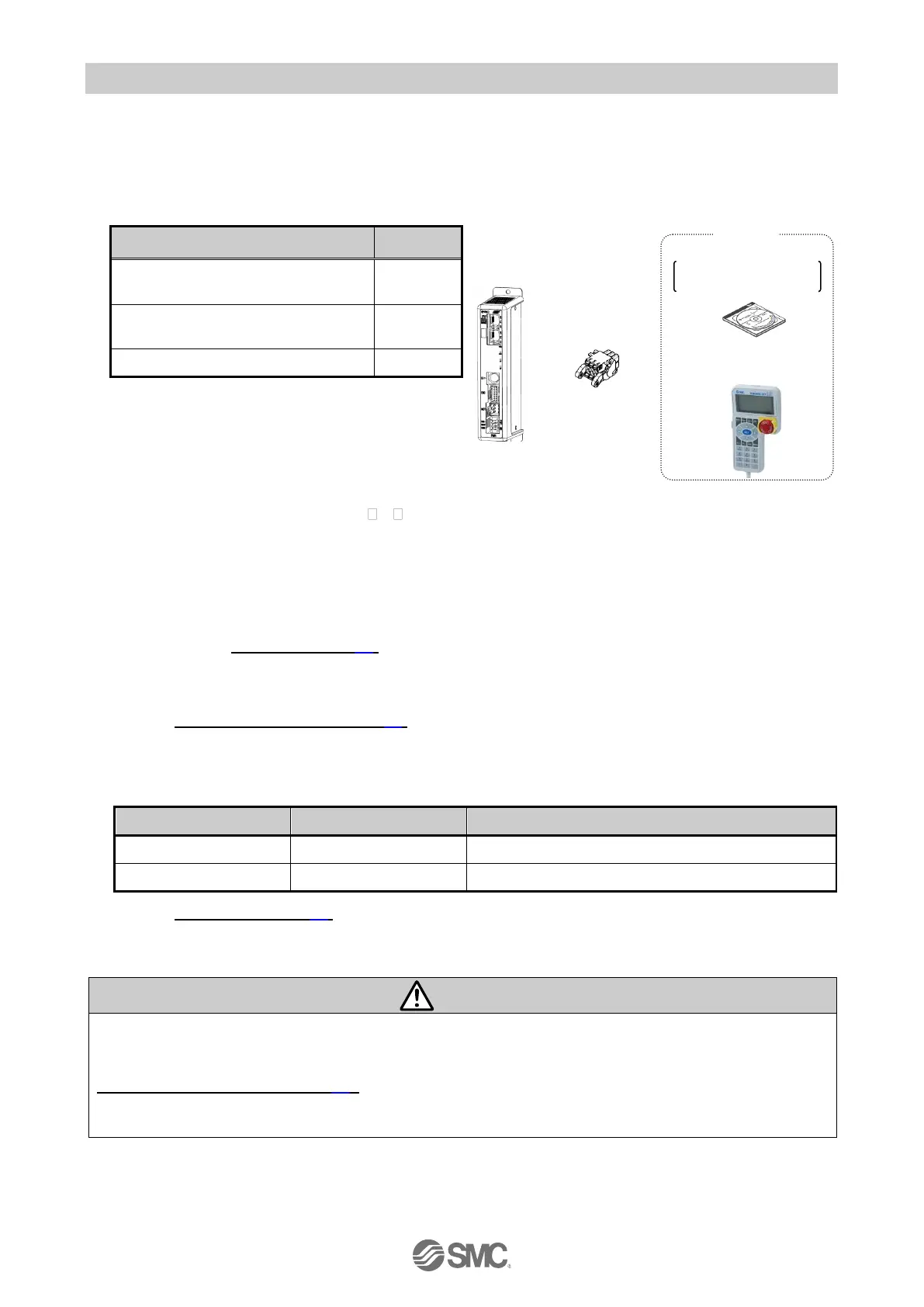
(1) Checking the contents of the package
After unpacking everything, check the description on the label to identify the controller and the
number of accessories. If any parts are missing or damaged, please contact your distributor.
Power supply plug
(JXC-CPW)
Power supply plug
(
JXC-CPW
)
1. These items are included when ordered
using the part number for an actuator set.
[Options]
•Teaching box (Part No: LEC-T1-3 G )
•Controller set up kit (Part No: JXC-W2)
(Controller setting software, communication cable,
USB cable and conversion unit are included)
•Conversion cable (Part No: P5062-5)
(2) Mounting the controller
Refer to section 3.4 Mounting (P.15) for instructions on how to mount the controller.
(3) Wiring and Connection
Connect the cables to the controller.
Refer to 5. External Connections (P.21) for the wiring of the connectors.
(4) Supply of power
Supply power 24VDC.
If the condition is normal, LED on the front of the controller turns ON as shown on the table below
Refer to
7. LED display (P.28)
for the explanation of LED lamps.
If the red [ALM] LED on the front of the controller (JXC) is ON, an alarm has been triggered.
When an alarm is generated
Refer to a corresponding memory of PROFINET or connect a PC or teaching box to the SI serial I/O
connector and check the details of the alarm. Then, remove the cause of the error referring to the
15. Alarm for Motor Control (P.62).
Please refer to the manuals of the controller setting software or the teaching box for details of the
alarms.
Controller set up kit
Cables & conversion unit
including
Teaching box
(Conversion cable is needed)

 Loading...


