- 57 -
13.3 Operation procedure for Operation by numerical instruction
E.g.) Input 50.00 [mm] to the position parameter of the specified step data and start the actuator.
For parameters other than position which are numerically specified (speed,
acceleration/deceleration), the values set for the specified step data are used.
Before starting the operation by numerical instruction, make sure that the servo is on and returning
to origin has completed.
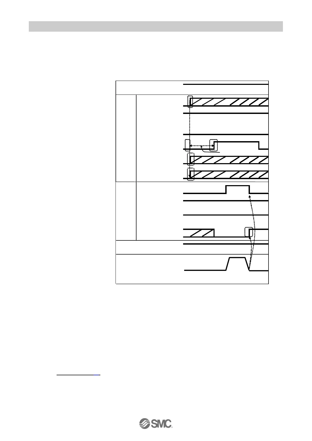
(1) Confirm that Byte4, bit0: Start
flag=OFF
Input Byte4, bit0: Start flag=OFF
when it is ON.
(2) Input the step data No. to be specified
by Byte0, bit0-5: IN0-5
E.g.) Specify step data No.1
→Byte0, Bit0: IN0=ON
Byte0, bit1-5: IN1-5= OFF
This is the Base step No that will
be used.
(3) Specify the numerical operation
input flags which control the
numerical operation data to be
entered, by Byte2, bit4-7,
Byte3, bit0-7.
Turn ON the relevant flag which
must be numerically input into the
specified step data and turn OFF
the relevant flag which is not
required.
E.g.) Only [position] of the numerical
operation data input flag must
be specified.
→Byte2, bit6=ON、
Byte2, bit4-5=OFF
Byte3, bit0-7=OFF
(4) Input Byte5, bit0-1: Movement
mode and Byte6-35:Numerical
operation data.
E.g.) Input [Position] 50.00 [mm].
5000[0.01mm]=(00001388)h
→Byte8: Position (HH)= (00) h
Byte9: Position (HL)= (00) h
Byte10: Position (LH)= (13) h
Byte11: Position (LL)= (88) h
(5) Input the numerical operation data input flag bit and numerical operation data, and then, input Byte4,bit0:Start flag= ON.
Operation instruction data will be transmitted when the start flag is ON.
(6) When the actuator starts operating, Byte1,bit0:BUSY=ON will be output.
Then, input Byte4,bit0:Start flag=OFF.
(7) When the actuator reached the target position, Byte1,bit3:INP=ON will be output.
(Refer to "INP" section (P.32) for signal ON conditions)
When the actuator operation completes, Byte1,bit0:BUSY=OFF is output.
The completion of the actuator operation is validated when both Byte1,bit3:INP=ON and Byte1,bit0:BUSY=OFF are
established.

 Loading...


