- 60 -
14.5 Controller Set up kit
The latest version of the controller setting software must be used.
Upgrade software can be downloaded from SMC website. http://www.smcworld.com/
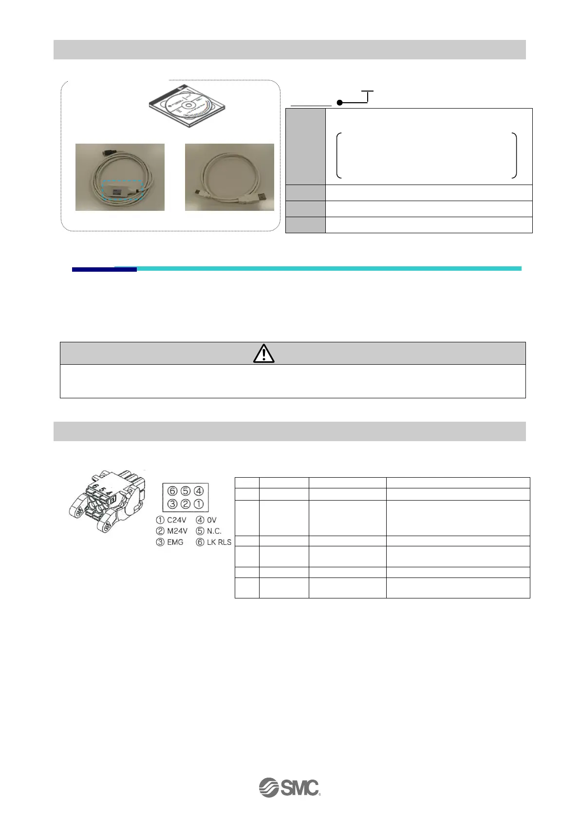
14.6 Power supply plug
JXC-CPW
Detail of Power supply plug
The positive control power.
The positive power for the
actuator motor to be supplied
via the controller.
The positive power for Stop signal
The negative common power for
M24V, C24V, EMG and LK RLS.
The positive power for lock
release.
PC/AT converter with Windows
®
XP (32bit), Windows
®
7(32/64bit), Windows
®
8.1(32/64bit) with
USB1.1 or USB2.0 port.
Windows
®
XP, Windows
®
7, Windows
®
8.1 are registered trademarks of Microsoft Corporation.
Controller set up kit
Kit contents
Controller set up software (CD-ROM)
Communication cable
Conversion unit
USB cable
Only Controller set up software (CD-ROM)
Only Communication cable & Conversion unit
Controller set up software (CD-ROM)
Communication cable
& Conversion unit

 Loading...


