EasyManuals Logo
Home>SMC Networks>Controller>JXCP1

SMC Networks JXCP1 User Manual

SMC Networks JXCP1
87 pages
To Next Page IconTo Next Page
To Previous Page IconTo Previous Page
Page #55 background imageLoading...
Page #55 background image
- 54 -
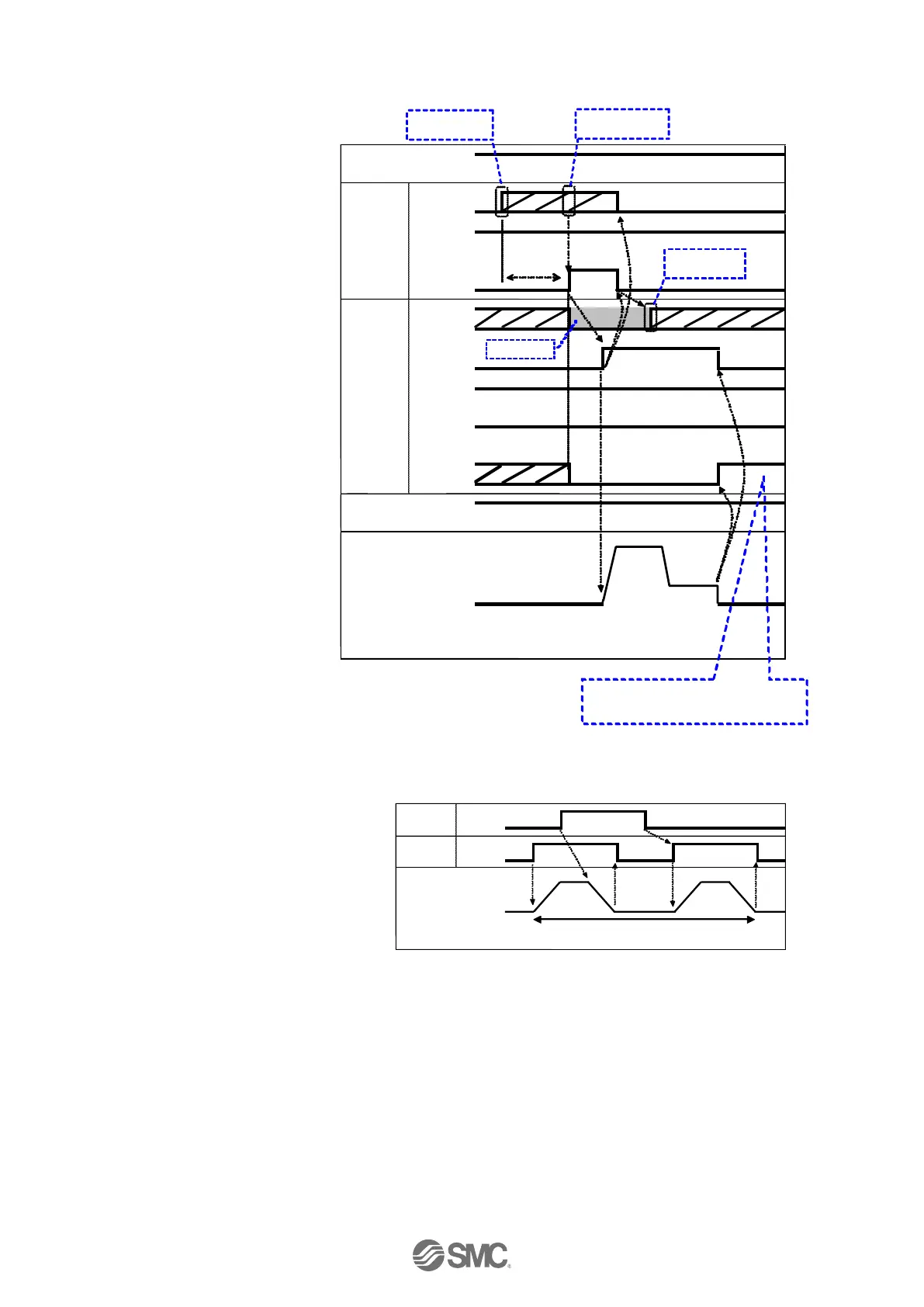
[3] Pushing Operation
- Procedure - - Timing chart -
(1) Input step data No.
(“IN0” to “IN5”)
(2) Turn ON the "DRIVE".
(“INP” turns OFF.)
→Scan the step data number
(from "IN0" to "IN5").
(3) "BUSY" is ON when pushing
starts.
After "BUSY" turns ON, if
"DRIVE" is turned OFF, the
step data number will be
output (from "OUT0" to
"OUT5").
(4) When "INP" turns ON and
"BUSY" turns OFF, the pushing
operation will be completed
(the actuator generates the
force larger than that specified
in "Trigger LV" of the step
data).
[4] HOLD
- Procedure - - Timing chart -
(1) During operation ("BUSY" is ON),
turn ON "HOLD".
(2) "BUSY" turns OFF.
(The actuator stops.)
(3) Turn OFF "HOLD".
(4) "BUSY" turns ON.
(The actuator restarts.)
Power supply
IN0 to 5
SVON
DRIVE
OUT0 to 5
BUSY
SVRE
SETON
INP
External lock
Pushing
operation
Input
signal
Output
signal
Speed
0mm/s
24V
0V
Unlock
Held
ON
OFF
ON
OFF
-
-
-
-
-
-
Input Step Data
No.
Read Step data
No.
Output Step
Data No.
-
-
-
-
-
-
-
-
-
-
INP signal turns ON when pushing
force exceeds the "Trigger LV" value of
step data.
Don’t care
More than twice
the communication
cycle time
HOLD
BUSY
HOLD during operation
Input
signal
Output
signal
Deceleration
Start point
Speed
0mm/s
ON
OFF
ON
OFF

Table of Contents

Questions and Answers:

Question and Answer IconNeed help?

Do you have a question about the SMC Networks JXCP1 and is the answer not in the manual?

SMC Networks JXCP1 Specifications

General IconGeneral
BrandSMC Networks
ModelJXCP1
CategoryController
LanguageEnglish

Related product manuals