When the operation is started and “DRIVE” is turned OFF,
the step No. executed by “DRIVE” will be refreshed/updated
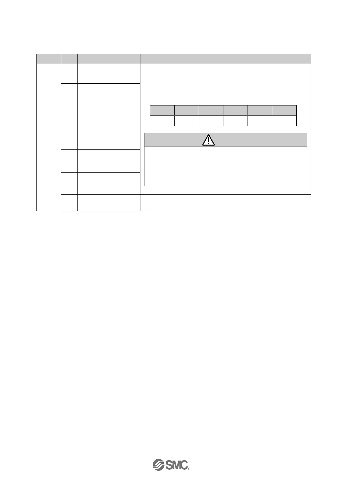
by the combination of “OUT0” to “OUT5” (binary digit).
(E.g.) Step data No.3 is output
(1) When “RESET” is turned ON, these signals turn OFF.
(2) During the alarm, these signals output the alarm group.
(3) During the pushing operation, if the actuator runs over
the defined pushing width, these signals turn OFF.

 Loading...


