- 64 -
15.3 Alarms and countermeasures
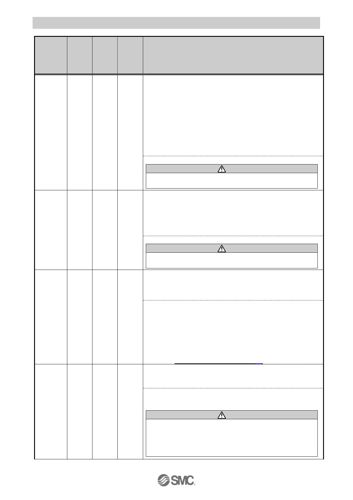
Name of the
controller
setting
software
(code) 1
Alarm contents/Countermeasure
Drive data
value is
wrong
(01-048)
<Condition>The step data is incorrect for the following conditions
(Settable range)
(1) Area1 <Area2
(If both Area1 and Area2 is 0, the alarm will not be activated.)
(2) Trigger LV ≤ Pushing force
(3) Minimum speed of actuator ≤ Pushing speed ≤ Speed
(4) Pushing speed ≤ Maximum pushing speed of actuator
(5) Pushing force ≤ Minimum pushing force of actuator
(6) Basic parameter "Maximum pushing force" ≥Minimum pushing force of
the actuator
(7) Basic parameters "Max pushing force" ≥ Threshold
<Countermeasure> Modify the step data and basic parameters setting
Please refer to the manual or the catalogue of the actuator for the
max/min pushing force/speed for the actuator.
Parameter
value is
wrong
(01-049)
<Contents> The basic parameter is not correct for the following condition:
(Settable range)
(1) Stroke(-) < Stroke (+)
(2) W-Area 1 < W-Area 2
( If both W-Area1 and W-Area2 is 0, the alarm will not be activated.)
(3) Maximum pushing force < Maximum pushing force of actuator
<Countermeasure> Modify the basic parameter setting.
Please refer to the manual or the catalogue of the actuator for the
maximum pushing force for the actuator.
Set step
data is not
registered
on list.
(01-051)
<Contents> For an operation for a specific step data no., the requested
number of the step data is not registered. (When operation is commanded
through PLC, this alarm will be generated depending on the signal interval
and the holding time of signals)
< Countermeasure >
(1) Make sure that the “Movement MOD” in the step data is not "Blank
(Disabled)" and that numbers [1(ABS)] and [2(INC)] or input in the
numerical instruction operation.
(2) Set the interval time between signals to more than twice the
communication cycle time, when signals are to be continuously input,
because PLC processing delays and controller scanning delays can
occur.
Refer to 13.2[2] Positioning operation (P.53)
Set stroke
is outside
the stroke
limit.
(01-052)
<Contents> The actuator goes outside the stroke limit specified by the
basic parameters, "Stroke (+)" and "Stroke (-)" if it performs the requested
operation. (Including JOG operation after return to origin)
<Countermeasure> Make sure that the basic parameters, "Stroke (+)" and
"Stroke (-)" are consistent with the distance of actuator movement
specified in the step data.
If the operation method of step data is "relative coordinated
movement", note the location where the operation starts and the
distance traveled. If the location is out of the stroke range when the
power is supplied, this alarm is generated. Move the table within
stroke range, and supply power.
 Loading...


