- 56 -
[7] Area output
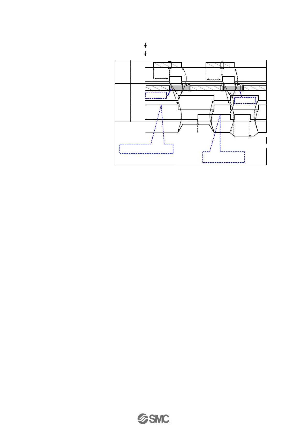
- Procedure - Timing chart
●Step data No.1 operation
(1) Input step data No.
(“IN0” to “IN5”)
(2) Turn "DRIVE" ON.
→ Receive the step data no.1
(from “IN0” to “IN5”).
(3) "BUSY" turns ON.
(The actuator starts the
operation.)
"INP" turns OFF.
After "BUSY" turns OFF, if
the "DRIVE" is turned OFF,
the step data No.1 ("OUT0"
to "OUT5") will be output.
(4) "AREA" of step data No.1 turns
ON. (at 150mm from the origin
point)
(5) "BUSY" turns OFF.
(The actuator stops.)
"INP" turns ON.
●Step data No.2 operation
(6) Input step data No. ("IN0" to "IN5")
(7) Turn ON "DRIVE".
Read step data No. 2 ("IN0" to "IN5")
(8) "AREA" turns OFF.
"BUSY" turns ON. (The actuator starts the operation.)
"INP" turns OFF.
After "BUSY" turns OFF, if "DRIVE" turns OFF, the step data No.2 ("OUT0" to "OUT5") will be
output.
(9) "AREA" of step data No.2 turns ON. (at 170mm from the origin point)
(10) "AREA" of step data No.2 turns OFF. (at 130mm from the origin point)
(11) "BUSY" turns OFF. (The actuator stops.)
"INP" turns ON.
If the current position is within the In
position range, the INP signal is ON.
Otherwise, the signal is OFF
If the current position is inside of 1, and 2
area scope for step data., the AREA signal
is ON. Otherwise, the signal is OFF

 Loading...


