ATyStM - 542931D - SOCOMEC
16 EN
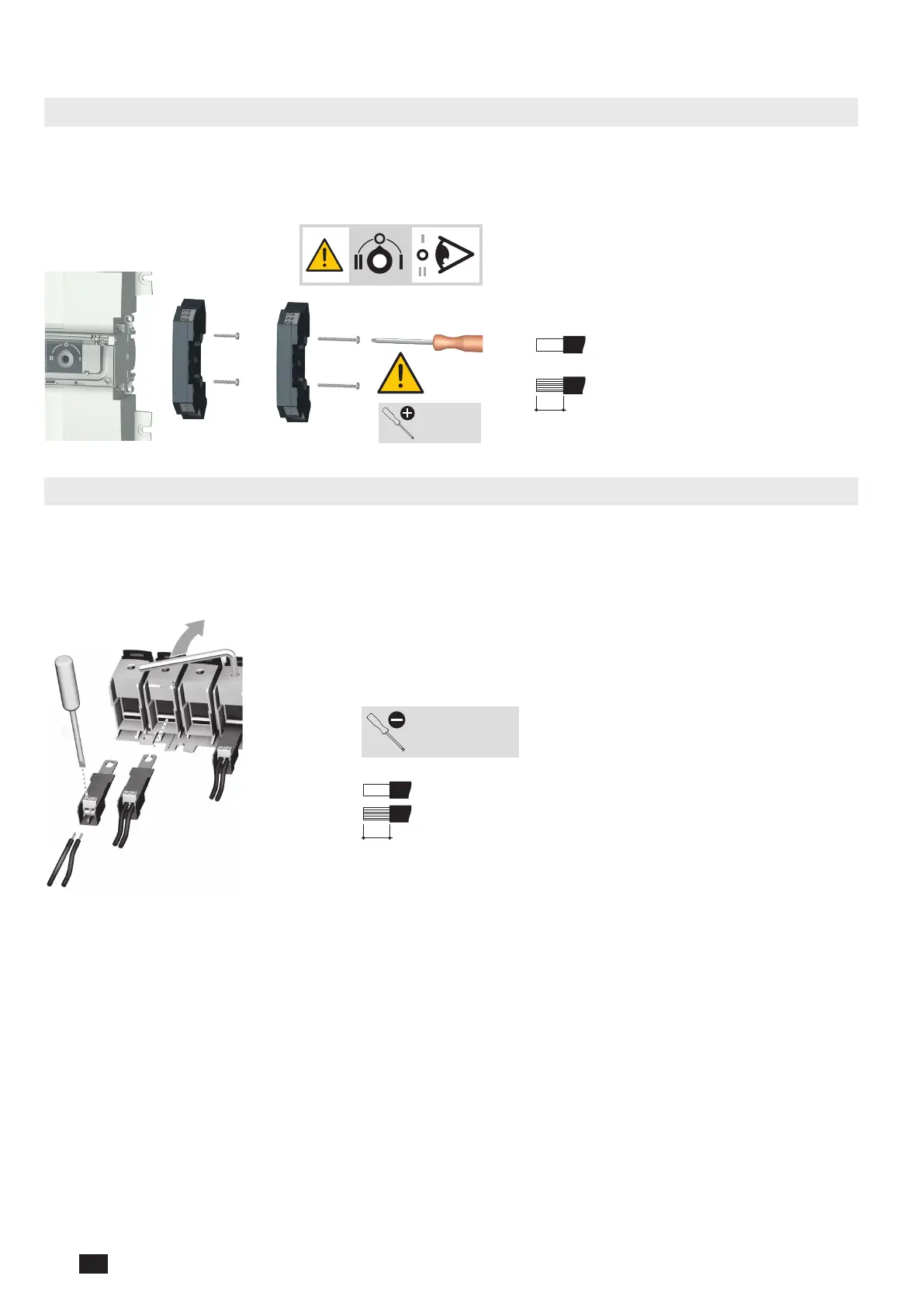
9. INSTALLATION OF OPTIONAL ACCESSORIES
9.1. Auxilliary contacts
Ref. 13091001 or ref. 13091011.
To t an additional AC, the switch must rst be put in the 0 position. An auxiliary contact module comprises: one NO/NC
or NOC changeover contact for each position (I-0-II). To install use the screws supplied with the module.
One module is factory tted.
10 mm
0,5 to 2.5 mm²
solid
stranded
0,5 to 1.5 mm²
PUSH-IN
Use 20mm
screws for
1 module
Use 35mm
screws for
2 modules
Posidriv PZ2
1 Nm
9.2. Voltage sensing and power supply tap
Ref. 1399 4006.
This provides 2 connection terminals for conductors with cross-section ≤1.5 mm².
The single pole terminals can be tted in any of the terminal cages without reducing the cage connection capacity.
2 parts/ref. Do not use in case of use of the bridging bar.
6 mm
Slotted head 3,5 mm
0,45 Nm
0,5 to 2,5 mm²
0,5 to 1,5 mm²

 Loading...


