ATyStM - 542931D - SOCOMEC
24 EN
13. OPERATION
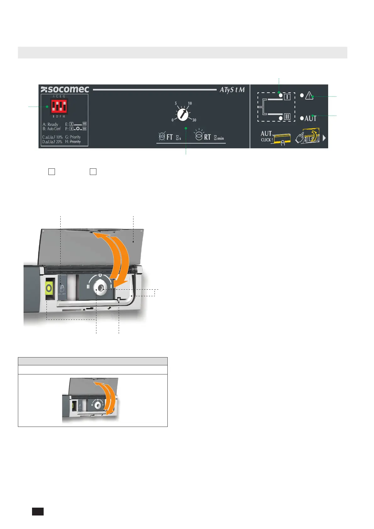
13.1. Presentation of the product interface
13.1.1. Product interface
4
3
2
5
1
1. Source
I
and Source
II
availability indicators
2. Fault LED
3. Auto LED
4. Potentiometers to set timers
5. Dip switchs
1 2
5
34
1. Locking
• Option to padlock using a 1 x 8 mm max. padlock.
2. AUT/MAN cover
• Open the cover to switch to manual mode.
• Close the cover to return to automatic (remote control) mode.
• Open and close the cover to clear faults.
3. Auto/Manual mode sensor
4. Switch position indicators
• Display of position I, 0, II.
5. Manual switching
• Insert the Allen key (5.0 mm) provided and turn to switch
manually.
• Manual operation is not possible when padlocked.
13.1.2. Reset
Operating fault reset
Open and re-close the AUT/MAN cover

 Loading...


