ATyStM - 542931D - SOCOMEC
21EN
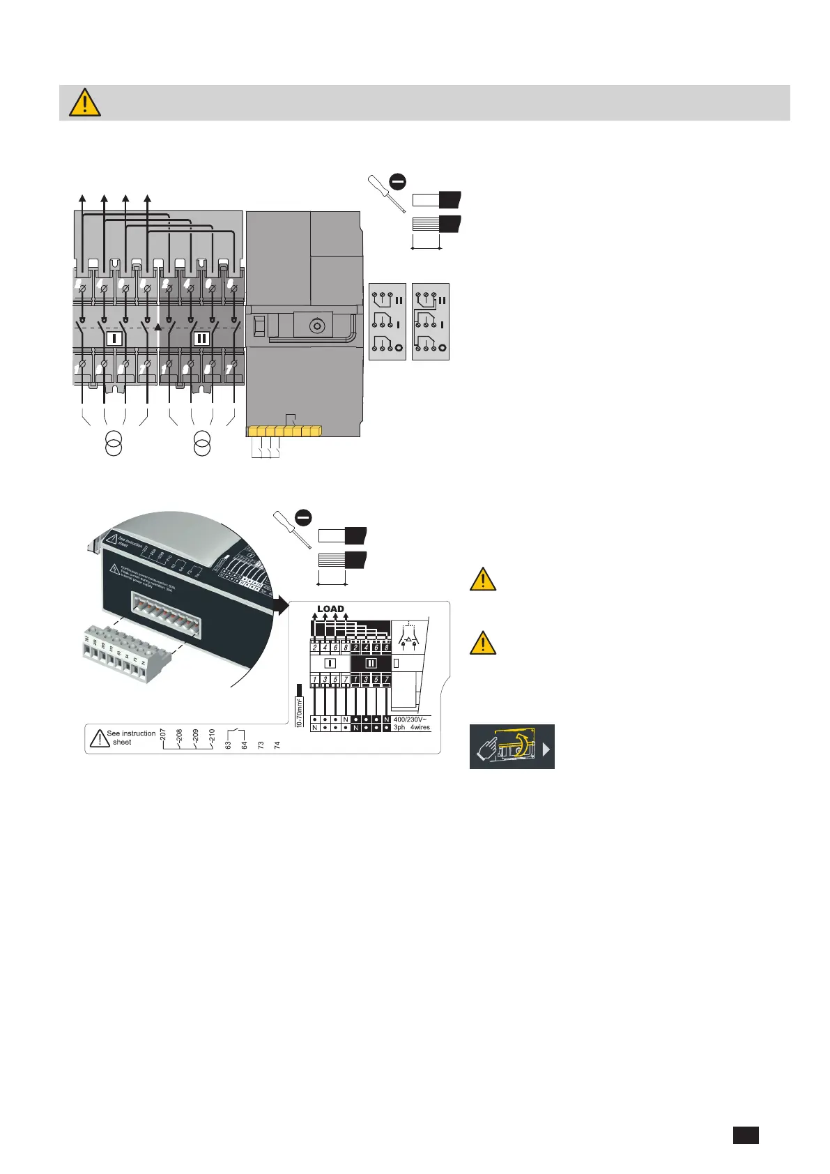
12. CONNECTION OF CONTROL/COMMAND CIRCUITS
Switch to manual mode before connecting the product. (Front Auto/Manu cover open). The product is
delivered in the 0 position.
Slotted head 3,5 mm 0,45 Nm
0,5 to 2,5 mm²
0,5 to 1,5 mm²
6 mm
1309 1001
1309 1011
LOAD SIDE
SI SII
207 208 209 210
63 64 73 74
6 mm /
Connection capacity
0,236 "
# 20 to # 14 AWG
0,5 to 2,5 mm
0,5 to 1,5 mm
2
2
# 20 to # 16 AWG
Slotted head 3 mm
3,97 lb-in 0,5 Nm
2 4 6
8
1
3
5 7
2 4 6
8
1
3
5 7
2 4 6 8
1 3 5 7
2 4 6 8
1 3 5 7
I1 I2 I3
O1
5 A AC1
250 Vac
22 24 21
11 14 12
01 04 02
5 A AC1
250 Vac
22 24 21
11 14 12
01 04 02
5 A AC1
250 Vac
22 24 21
11 14 12
01 04 02
5 A AC1
250 Vac
22 24 21
11 14 12
01 04 02
5 A AC1
250 Vac
22 24 21
11 14 12
01 04 02
Ensure that the product is in Manual Mode
(front cover open).
Slotted head 3 mm 0,5 Nm
0,5 to 2,5 mm²
0,5 to 1,5 mm²
6 mm
All pressure on the connector pins is to be avoided
during wiring of the auxiliary cables.
The product is delivered in the 0 position and in
auto mode. Maximum control cables length =10m.
In case of longer distance, use control relays.
Source must always be connected as show above.
4P

 Loading...


