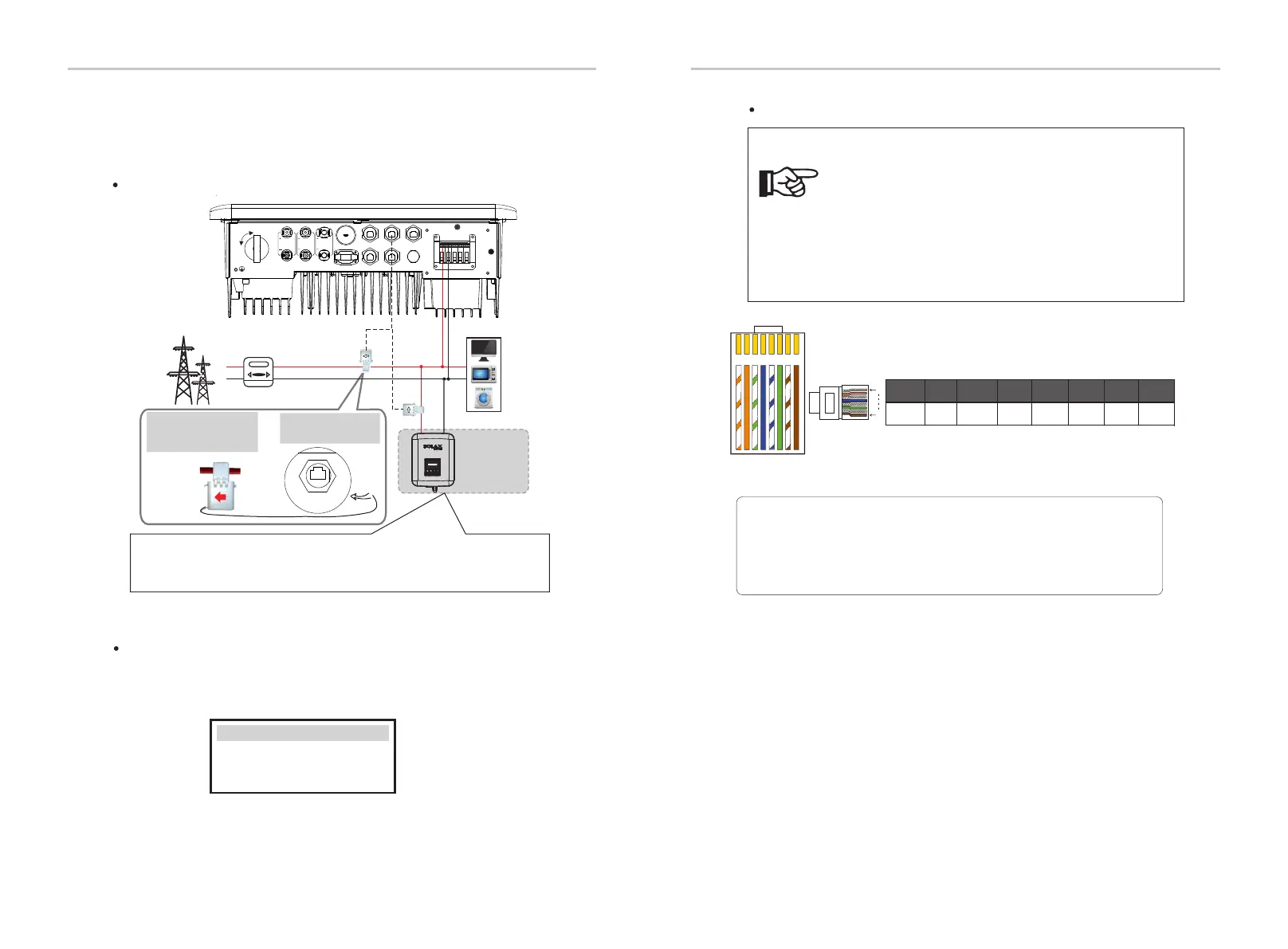
CT Connection
Ø
CT connection diagram
The current sensor measures the current on the live wire between the
inverter and the public grid.
Note for CT connection:
• Do not place the CT on the N wire or ground wire.
• Do not put CT on the N line and L line at the same time.
• Do not place the CT on the side where the arrow points to
the inverter.
• Do not place the CT on non-insulated wires.
• The cable length between CT and inverter should not
exceed 25 meters.
• After CT is connected, prevent the CT clip from falling off.
It is recommended to wrap the CT clip around in circles with
insulating tape.
Note!
L Line
CT
Public grid
electricity
Meter/CT port is at the
bottom of the inverter.
Note:The arrow on the CT
must point at the public
grid.
Meter/CT
LCD settings
To select CT, you need to enter Use setting ,then enter CT/Meter
Setting.
>Select
CT
CT/Meter Setting
50
51
Electrical Connection
Electrical Connection
1 2
3
4
5
6 7 8
1
8
1
2 3 4 5 6 7 8
485A 485B X
CT1-2CT1-1
CT2-2
CT2-1
X
Note!
Only one of the Meter and CT connections can be selected.
Meter cable goes to pin terminal 4 and 5;CT cable goes to pin
teminal 1 and 8; reserved CT cable goes to pin terminal 3 and 6.
Grid
Household Meter
Loads
L
N
Other power
generation
equipment
X1X1
CT 1
CT 2
If the user has other power generation equipment (such as inverters) at home
and wants to monitor both, X1-Hybrid G4 inverter provides CT2
communication function to monitor the power generation equipment.
ON
OFF
PV 1
PV 2
BAT
BMS
CAN
DRM
Upg rade
Don gle
Met er/CT
COM /LCD

 Loading...