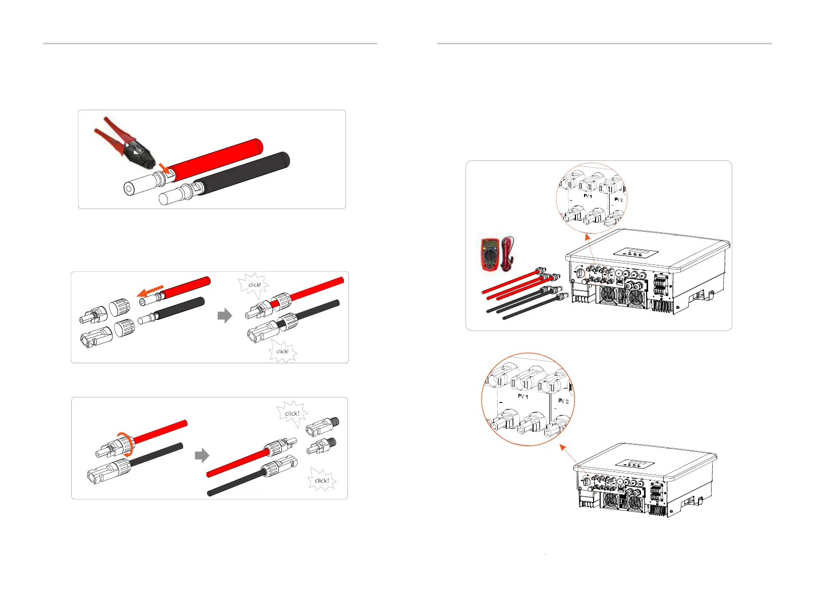
Step 6. Tighten the fastening head and into insert the corresponding
positive and negative (PV-/PV+) ports of the inverter.
The following is the location of the inverter's positive and negative
(PV-/PV+) ports.
Note: Before inserting the PV connectors, please turn on the switch
of the PV module and use a multi-meter to measure the positive
and negative poles of the PV connectors to prevent reverse
connection.
Schematic diagram of the inverter PV connected.
Crimping Tool
PV+
PV-
Positive PV connector
Positive PV
connector
Negative PV connector
Electrical Connections
Electrical Connections
34 35
PV 2+
PV1+
PV1-
PV1-
PV 2-
PV1+
Multimeter
DC Voltage
Range ≥1100 V DC
D
o
n
gle
/Up
gr
a
d
e
D
o
ngl
e
/U
pg
rad
e
Negative PV connector
Step 5. The PV connectors are divided into 2 parts - the plug and the
fastening head. Insert the cable through the fastening head and the
opposite plug. Note that the red and black lines correspond to
differentof plugs. Finally, force the cable pair into the plug, will a
"click" sound,which indicates that the connection is complete.
Step 4. Tighten the PV pin needle and the wiring harness to make the
connection tight without looseness.

 Loading...


