1) Users can customize the length of the CT communication cable. The
accessory package provides 1*RJ45 and 1*waterproof connector with
RJ45 terminals.
When the CT cable is completed, connect the A terminal to the
"CT/METER" port of the inverter and tighten the waterproof screw, and
connect the B terminal to the RJ45 coupler.
A
B
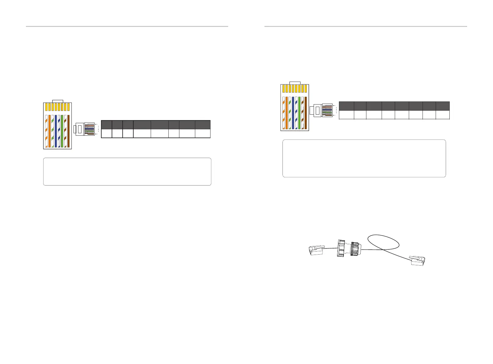
METER/CT pin is defined as follow:
Ø METER/CT communication cable
Note!
Only one of the Meter and CT connections can be selected.
Meter cable goes to pin terminal 4 and 5; CT-R cable to PIN
Terminal 1 and 8; CT-S cable to PIN Terminal 2 and 7; CT-T cable is
connected to terminals 3 and 6.
1 2
3
4
5
6 7 8
1
8
1
2 3 4 5 6 7 8
485A
485B
CT-T-2 CT-R-2CT-R-1 CT-S-2CT-T-1CT-S-1
Electrical Connection
Electrical Connection
66
67
The BMS pin is defined as follows:
Ø BMS communication cable
Note!
The communication port on the lithium battery must be
consistent with the definition of pins 4, 5, 7, and 8 above;
1 2
3
4
5
6 7 8
BMS_CANH
x
BMS_485A
X X
X
1
2
3
4
5
6 7 8
1
8
BMS_CANL
BMS_485B
Step 7: Finally, find the corresponding COM, BMS, Meter, CT, CAN, DRM,
OFF poets on the inverter and insert the communication cable into the
corresponding ports.

 Loading...


