13 • Recommended Wiring Scheme
________________________________________________________________________________________________
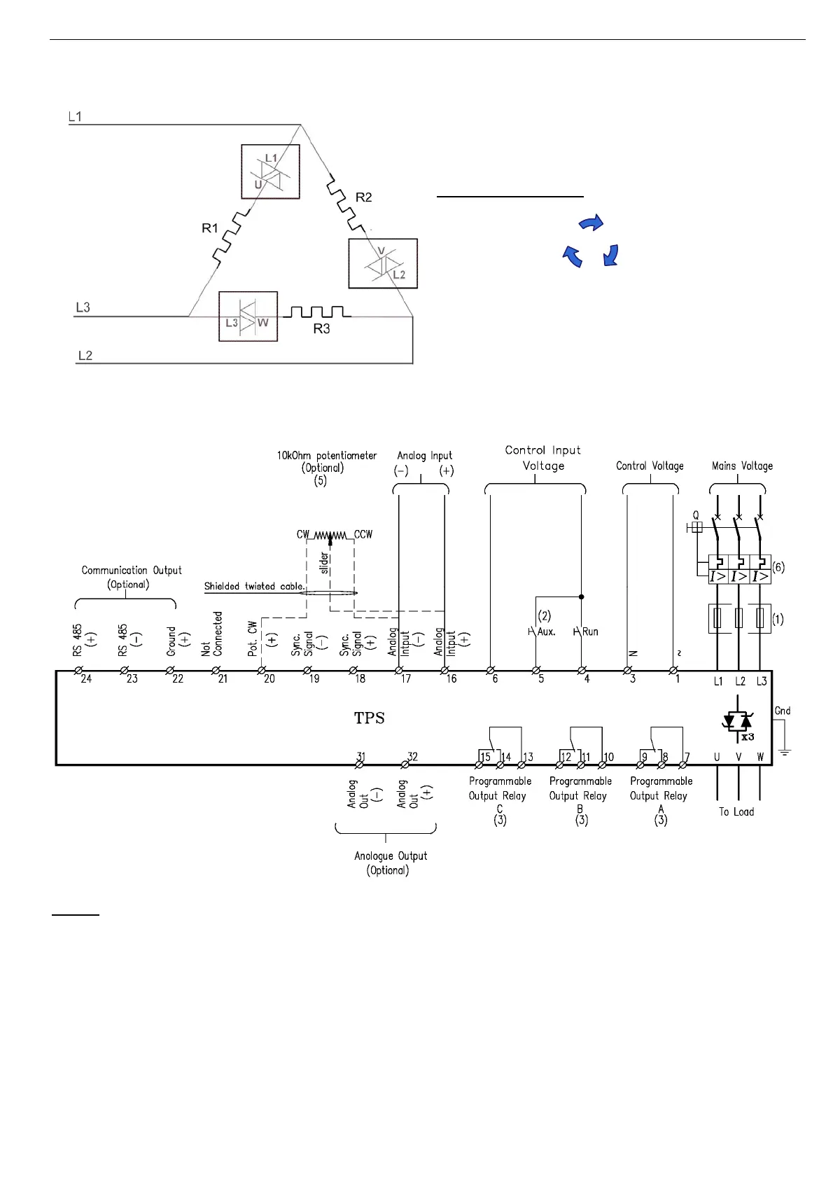
4.2 INSIDE DELTA Wiring
When the TPS is connected INSIDE DELTA wiring must be exactly as in the following diagram:
L1-U, L2-V, L3-W represent the three controlled TPS
phases.
R1, R2 R3 represent the load.
L1, L2, L3 are mains voltage.
Verify the following:
Phase sequence as below:
Phase L1-U of the TPS is connected between L1
and L3 of the mains.
Phase L2-V of the TPS is connected between L1
and L2 of the mains.
Phase L3-W of the TPS is connected between L2
and L3 of the mains.
4.3 Typical control scheme
Notes:
(1) - Use fuses for thyristors short circuit protection. Refer to section
4.5.1 on page 15
Note: In 1000V models semiconductor protection fuses for “type 2 coordination" are built –in.
(2) - For Aux. input programming refer to section
7.7.2 on page 30.
(3) - For programmable output relays A, B &C refer to section
7.7.2 on page 30.
(4) - When emergency Stop switch is required it is recommended to trip a series contactor or the
feeding circuit breaker. (Not shown)
(5) – Potentiometer control is only possible if option P (Potentiometer control) is ordered.
(6) – Only short current protection is mandatory in models other than 1000V. The TPS has a
built-in over current protection.
L2
L3
L1