28 • Control Keypad
________________________________________________________________________________________________
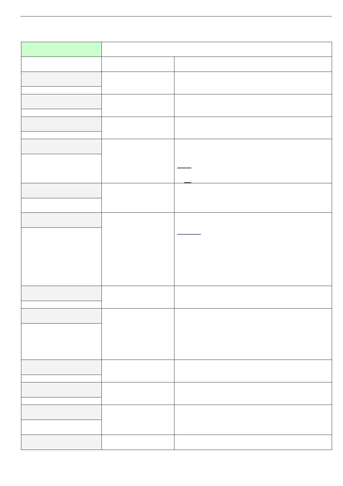
7.7.1 Main parameters settings – page 1
MAIN PARAMETERS
SETTINGS
Display and default
values
Range Description
LINE VOLTS (Vn)
400V
120V-1000V Sets TPS mains voltage
LINE FREQUENCY
50 Hz
50Hz, 60Hz Sets TPS mains frequency
TPS RATED CURR.
100 AMP.
8A-3000A Sets TPS RATED CURRENT (FLC)
TPS RATED CURRENT should be as shown on the
TPS Name plate. (Refer to section
6.1 on page 20)
LOAD RATED CURR.
100 AMP.
8A-3000A Sets LOAD RATED CURRENT (FLA).
Should be programmed as shown on load’s name
plate.
Note:
LOAD RATED CURRENT≤TPS RATED CURRENT
in all 3 phases.
LOAD RATED POWER
69.3 KW
0.1kW-
3600kW
Sets load rated power.
This parameter is set to enable the TPS to close a
control loop when in PHASE CONTROL- POWER
mode of operation. Refer to section
3.8.4 on page 10.
CONNECTION TYPE
WYE, NEUTRAL CON
INSIDE DELTA,
DELTA,
WYE, NEUTRAL NC,
WYE, NEUTRAL CON
Sets connection mode of the TPS.
Refer to section 4.1 on page 12.
Caution:
WYE, NEUTRAL NC applicable for symmetrical loads
only. Connecting to non symmetrical loads might
damage the load!
When WYE, NEUTRAL NC applies set the
UNBALANCE protection to the lowest practical value
and trip the TPS upon UNBALANCE or else load will
damage. Refer to section
7.7.3 on page 32.
LOAD POWER FACTOR
1.0
0.00-1.0
Sets load rated power factor.
FIRING METHOD
ZERO CROSSING
PC TO ZC 1 SEC.
.
.
PC TO ZC 3600 SEC.
PH. CTRL – POWER
PHASE CONTROL
ZERO CROSSING
Sets TPS mode of operation
Refer to section
4.1 3.8 on page 9.
CONTROL MODE
INPUT SIGNAL
INPUT SIGNAL Reserved for future enhancement.
ON-OFF CYCLE T
2.0 SEC.
1.0sec. – 10sec. Sets TPS cycle time when operating in ZERO
CROSSING. Refer to section 3.8.1 on page 9.
TURN ON DELAY
0.0 SEC.
0.0sec. – 60sec. Sets TPS ON DELAY. This feature is used when
several units get ON command instantaneously.
Programming different delays will prevent sudden
loading the supply.
TURN OFF DELAY
0.0 SEC.
0.0sec. – 60sec. Sets TPS OFF DELAY. This feature is used when
several units get OFF command instantaneously.