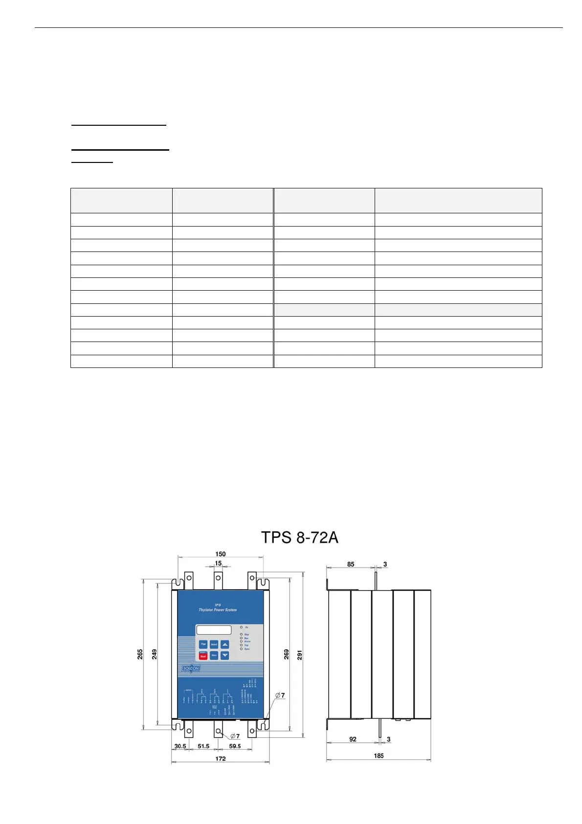
15 • Dimensions
________________________________________________________________________________________________
4.5.1 Short Circuit Protection
For “type 2 coordination”, use fuses for semiconductor protection to protect the TPS from a short circuit.
Fuses for semiconductor protection give excellent results because they have low I²t values and high
interruption ratings.
Recommended fuse selection procedure:
(1) Fuse rated voltage: Choose minimum fuse rated voltage which is above the rated voltage of the
mains.
(2) Fuse rated current: Select a fuse which is 1.6 times the rated TPS current
(3) Fuse I²t: Verify that the I²t value of the fuse is less than or equal to the I²t value of the thyristor in the
TPS as shown in the table below.
(4)
TPS Model Max. Thyristor I
2
t
[A
2
Sec]
TPS Model Max. Thyristor
I
2
t [A
2
Sec]
TPS-8 5,000 TPS-390 200,000
TPS-17 5,000 TPS-460 700,000
TPS-31 5,000 TPS-580 700,000
TPS-44 5,000 TPS-820 700,000
TPS-58 12,000 TPS-950 Consult Factory
TPS-72 12,000 TPS-1100 Consult Factory
TPS-85 12,000 TPS-1500 Consult Factory
TPS-105 15,000
1000V Models Installed fuses (A
2
Sec)
TPS-145 60,000 TPS-55 1000V Bussmann 170M3243 (16000)
TPS-170 60,000 TPS-105 1000V Bussmann 170M3243 (16000)
TPS-210 140,000 TPS-160 1000V Bussmann 170M3245 (54500)
TPS-310 200,000 TPS-200 1000V Bussmann 170M3246 (115000)
Note: In 1000V models semiconductor protection fuses for “type 2 coordination" are built –in.
The fuses listed under “installed fuses” in the table above are recommended, however equivalent fuses from
other manufacturers can be used as well as long as their I
2
t values are equal or lower to the values mentioned
in parentheses.
4.5.2 Transient Protection
Line transient voltages can cause a malfunction of the TPS and damage to the thyristors. All TPS units
incorporate Metal Oxide Varistors (MOV) to protect from normal line voltage spikes.
When higher transients are expected, additional external protection should be used (consult factory).
5. DIMENSIONS
5.1 400-690VAC Models