EasyManuals Logo

Solcon TPS User Manual

Solcon TPS
42 pages
To Next Page IconTo Next Page
To Previous Page IconTo Previous Page
Page #9 background imageLoading...
Page #9 background image
9 • Technical Data
________________________________________________________________________________________________
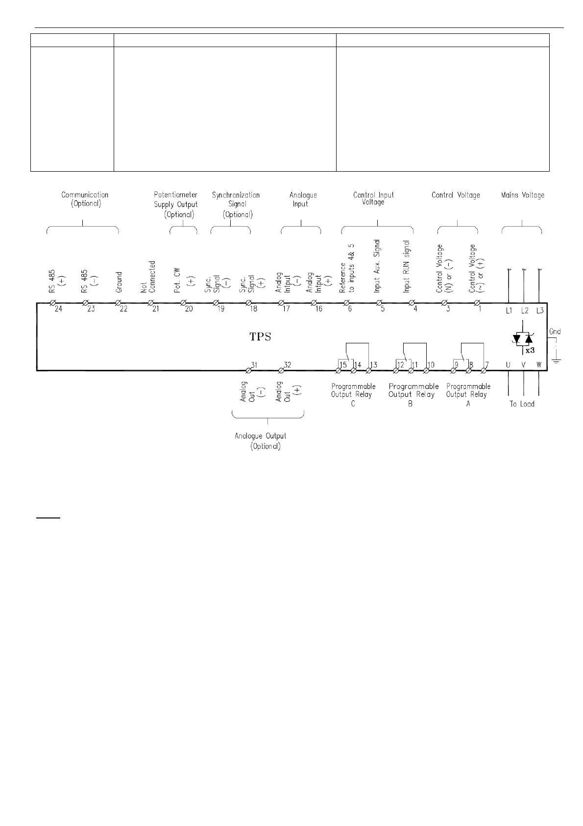
Indication Description Remarks
(-) OUT Analogue output (-)(Optional) configured as 4-20mA, 0-20mA or 0-10V.
Refer to section
6.6 page 21 for hardware
settings. .
Analogue output can be programmed as a
signal proportional to output power or
average of 3 phase currents or I1 or I2 or
I3 or as a reflection of the analogue input
to the TPS.
Refer to section
7.7.2 page 30 for
programming analogue output.
3.6 Input / Output indication
3.7 Load Connections
The TPS can be connect the load as shown in section
4.1 on page 12. The available configurations are:
Wye with Neutral Connected, Wye with Neutral not Connected, Delta or inside Delta.
Load connection type must be programmed to TPS. Refer to section
7.7.1 page 28.
Note:
Any number of parallel branches may be connected in the shown connection types provided that the total
connected load will not exceed the current rating of the TPS unit.
3.8 Modes of operation
3.8.1 Zero Crossing
In this mode of operation thyristor’s firing is performed so that current starts at its zero crossing point .
Main advantages of this mode are:
Minimizing RFI noise.
Minimizing current THD.Main disadvantages are:
No “Soft start”.
High inrush current in case of load with temperature dependant characteristic (lower resistance when
cold)
Current may vary in time.
In this mode of operation the TPS is programmed to operate in a cycle. (Tct)
When, during this cycle, analogue input is set to maximum – The TPS will conduct continuously.
When analogue input is lower, a proportional number of waves will be delivered to the load during Tct.
Firing method must be programmed to TPS. Refer to section
7.7.1 page 28.

Table of Contents

Questions and Answers:

Question and Answer IconNeed help?

Do you have a question about the Solcon TPS and is the answer not in the manual?

Solcon TPS Specifications

General Specifications IconGeneral Specifications
rated current8-1500A
rated voltage120 - 1000VAC +10% -15%
control voltage120 or 230VAC, 110VDC+10% -15%
frequency50 / 60 Hz
controlled phasesThree
short-circuit current25kA
rated insulation voltage690V (120-690V mains models), 1000V (1000V mains models), 250V (control circuits)
rated impulse withstand6kV (Mains), 2.5kV (control)
degree of protectionIP00
pollution degree3
ambient temperature operating-10 – + 50°C
ambient temperature storage-20 – + 70°C
altitudeTo 1000 m ASL W/O de-rating
coolingForced air (fans)
number of CTsThree
connection modesWye - Neutral connected / not connected
Control Specifications IconControl Specifications
control methodDigital
firing methodZero crossing, Phase control, Phase control-power
on-off time cycle1000 – 10000 mSec.
analog input0-10V >100KΩ / 4-20 mA, 0-20mA <100Ω
control inputsStart/Stop (with internal 0-60 sec time delays), Aux. contact
output relays3 programmable (1-C/O) (8A/250VAC)
maximum breaking capacity AC2000 VA
max. DC load breaking capacity8A at 30VDC.
synchronizationOne master and 2-9 connected slaves
Fan and TPS Consumption Ratings IconFan and TPS Consumption Ratings
TPS 8-31A consumption21W
TPS 44-72A consumption36W
TPS 85-105A consumption26W
TPS 145-170A consumption35W
TPS 210-460A consumption64W
TPS 580-820A consumption100W
TPS 55-200A 1000V consumption40W

Related product manuals