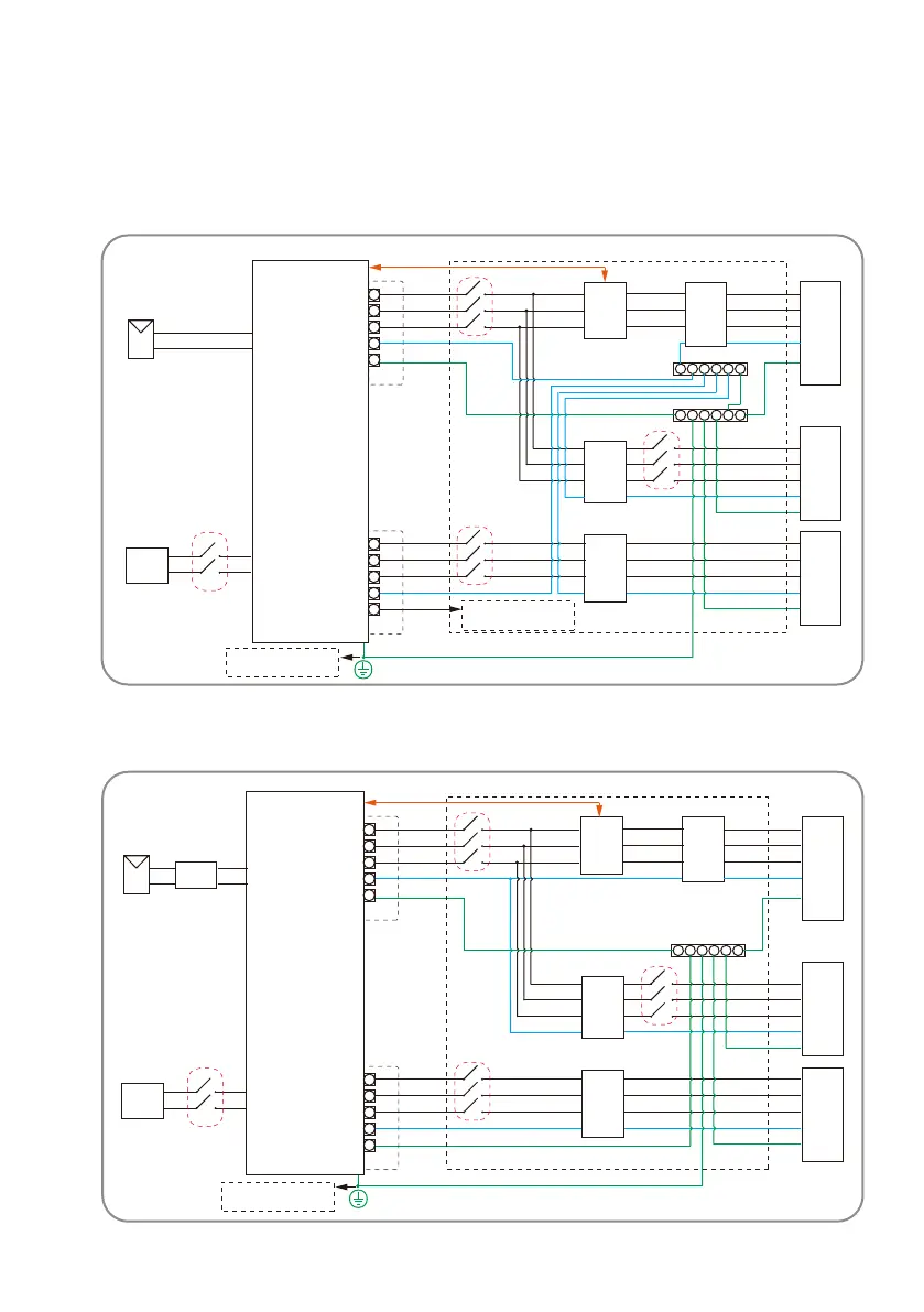
or other countries, the ollowing diagram is an eamle or grid systems without secial reuire
ment on wiring connection.
The system diagram o this roduct as ollow
or Australia and ew ealand, the neutral cable o ngrid side and acku side must be
connected together according to the wiring rules ASS . therwise the backu unction
will not work.
P
Grid
Grid
L1
L2
L3
N
PE
L1
L2
L3
N
PE
L1
L2
L3
N
PE
CD
CD
ar
PE Link
CT
CT
CT
ain
eter
Normal
Loads
acku
Loads
Load
PEar
attery
×
Dont connect this terminal or
Australian and ew ealand grid
system
The additional grounding screw
hole at the lower right conner.
Inverter
AC reaker
AC reaker
CT C
DC reaker
AC reaker
P
Grid
Grid
L1
L2
L3
N
PE
L1
L2
L3
N
PE
L1
L2
L3
N
PE
CD
CD
CT
CT
CT
ain
eter
Normal
Loads
acku
Loads
Load
PEar
attery
×
The additional grounding screw
hole at the lower right conner.
Inverter
CT C
AC reaker
AC reaker
DC reaker
AC reaker
UM0035_ASW05-12kH-T2-T3_EN_V01_0523
 Loading...