MPI-536 – USER MANUAL
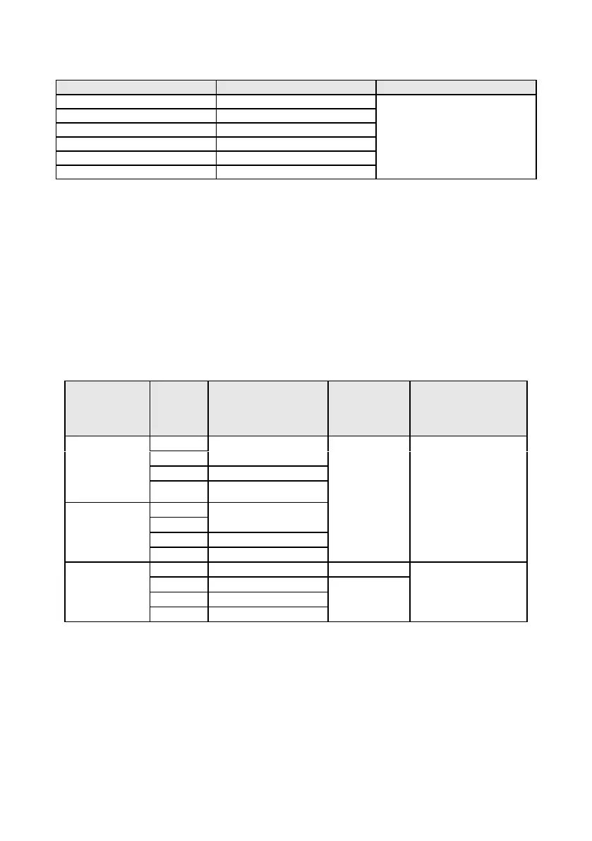
Indications of short-circuit current I
k
Test range according to IEC 61557-3 can be calculated on the basis of test ranges for Z
S
and nominal
voltages.
Calculated on the basis of
accuracy for fault loop
Prospective fault current calculated and displayed by the meter may slightly differ from the val-
ue calculated by the user with a calculator, basing on the displayed value of the impedance,
because the meter calculates the current from unrounded value of fault loop impedance (which
is used for displaying). As the correct value, consider I
k
current value, displayed by the meter or
by firmware.
10.1.5 Measurement of parameters of RCD
Measurement of RCDs type: AC, A, B, B+, F, EV
Rated operating voltage U
n
: 110 V, 115 V, 127 V, 220 V, 230 V, 240 V
Operating voltage range: 95 V…270 V
Rated mains frequency f
n
: 50 Hz, 60 Hz
Operating frequency range: 45…65 Hz
RCD trigger and response time test t
A
(for measurement function t
A
)
Test range according to IEC 61557-6: 0ms ... to the upper limit of displayed value
Setting
of multi-
ple val-
ues
▪ General type
▪ Short-time de-
lay type
▪ AC module in
EV type
0..300 ms (TN/TT)
0..400 ms (IT)
1)
for I
n
= 10 mA and 0.5 I
n
accuracy is ±(2% m.v. + 3 digits)
2)
for measurements acc. to IEC 62955
3)
for measurements acc. to IEC 62752
Accuracy of differential current setting:
for 1*I
n
, 2*I
n
, 5*I
n
..................................................................... 0..8%
for 0.5*I
n
.................................................................................... -8..0%