MPI-536 – USER MANUAL
3.4 Fault loop parameters
NOTE!
If there are residual current devices in the network tested, they should be bypassed
by bridging for the period of impedance measurement. However, it should be re-
membered that the tested circuit is modified in this way and the obtained results
may slightly differ from the actual results.
After completing measurements, always remove modifications introduced to the
tested system for the period of measurements and check the operation of the resid-
ual current switch.
The above remarks do not apply to measurements of fault loop impedance with the
use of function Z
L-PE [RCD]
.
Measurements of short-circuit loop impedance downstream the inverters are inef-
fective and measurement results unreliable. This is due to the fluctuations of inter-
nal impedance of the inverter during its operations. Do not perform measurements
of short-circuit loop impedance directly downstream inverters.
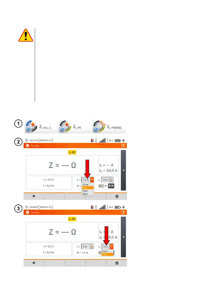
3.4.1 Settings of measurements
Select item Z
L-N, L-L
, Z
L-PE
or Z
L-PE[RCD]
.
The correctness of the measure-
ment depends on the correct ad-
justment of the length of leads.
If a WS type adapter has not
been connected to the meter,
standard manufacturer's lead
lengths are available in the menu.
In this case, touch the drop-
down list field.
Select the required lead length.
The prospective short-circuit cur-
rent I
k
can be calculated based on
one of two values:
rated network voltage U
n
,
voltage measured by the me-
ter U
0
.
The physical meaning of the pa-
rameter is presented in section
3.4.5.
Touch the drop-down list field.
Select the required value.