MPI-536 – USER MANUAL
3.4.5 Prospective short-circuit current
The meter always measures fault loop impedance Z
S
and the displayed short-circuit current is
calculated according to the following formula:
where:
Z
S
– measured impedance,
U – voltage dependent on the network rated voltage settings U
n
(section 3.4.1 point ):
where:
U
n
– nominal voltage of the network,
U
0
– voltage measured by the meter.
On the basis of U
n
rated voltage selected (section 2.2.1), the meter automatically recognizes
the measurement at phase voltage or phase-to-phase voltage and takes it into account in the calcula-
tions.
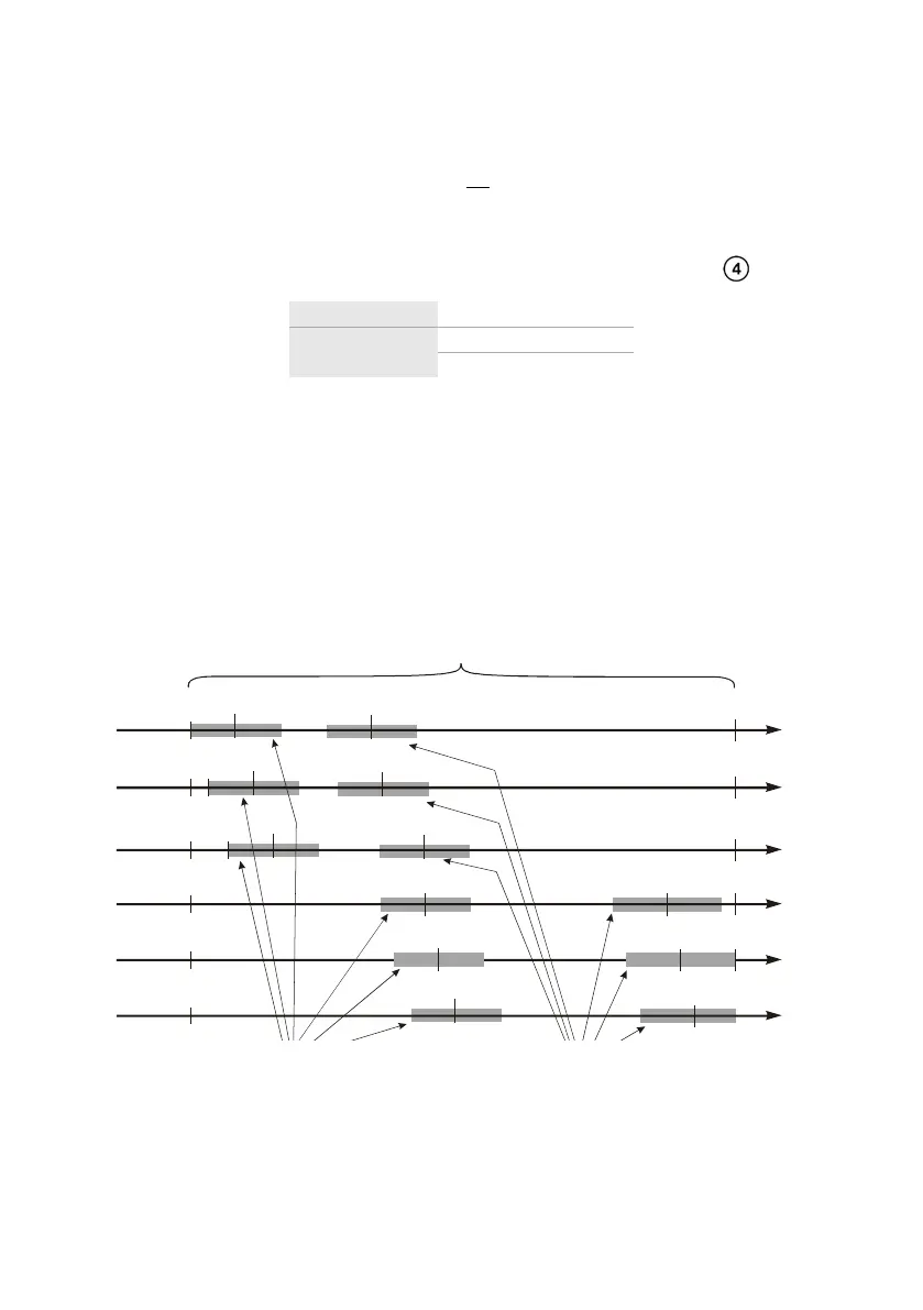
If the voltage of the network being tested is outside the tolerance range, the meter will not be
able to determine a proper rated voltage for the short-circuit current calculation. In such a case, – – -
will be displayed instead of short-circuit current value. Fig. 3.6 shows voltage ranges for which short-
circuit current value is calculated.
230
400
440
U [V]
Zakresy napięć U , dla których
liczony jest prąd zwarciowy
L-N
Zakres napięcia, dla którego wykonywany
jest pomiar impedancji
207
253
360
115
127
180
200
220
220
380
418
198
242
342
373
415
440
216
240
264
103
440
U [V]
440
U [V]
U [V]
U =115 V
n
U =220 V
n
U =230 V
n
U =240 V
n
Zakresy napięć U , dla których
liczony jest prąd zwarciowy
L-L
110
121
171
190
209
99
440
U [V]
U =110 V
n
127
140
198
220
242
114
440
U [V]
U =127 V
n
99
99
99
99
99
Fig. 3.6 Measuring voltage ranges
The voltage range for which the impedance measurement
is performed
The voltage range U
L-L'
for which the short-
circuit current is calculated
The voltage range U
L-N'
for which the
short-circuit current is calculated