1-3 (E)
CA-550
CA-550P
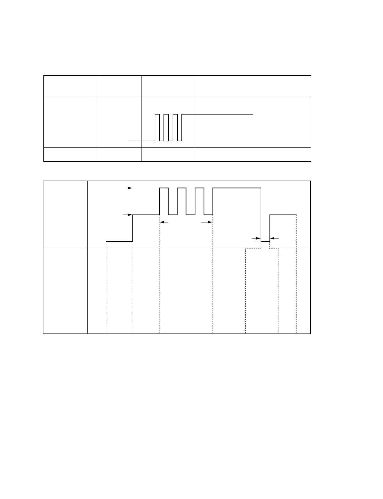
Note1: Specifications of BATT IND Signal
VTR has a battery voltage detection and waring signal generation circuits and it sends the signal shown
below to the camera.
Battery Terminal
Voltage
(VTR internal battery)
12.0—11.1 Vdc 11.1—10.8 Vdc
10.8 Vdc —
2—3 Vdc
across 300 Ω
0 V
Input Signal at
Pin 13
LED on Viewfinder
1.0 ± 0.2 Hz
duty 50 ± 10 %
Stays out Blinks at 1 Hz Lights up
Note2: Specifications of REC ALARM Signal
Input Signal at
Pin 15
5.0
REC ALARM
signal
1.0 ± 0.2 Hz
duty 50 ± 10 %
REC RESET signal
10—100 msec
VTR Action
Power
OFF
Power
ON
When VTR changes
from POWER SAVE
to REC START mode,
or when the servo is
lost
When VTR
changes from
STANDBY to
REC START
mode, or in
REC mode
At the end of
tape or When
VTR is put
into STOP
mode by itself
(REC RESET
signal does
not appear
when VTR is
put into STOP
mode by
operating the
camera)
STOP
mode
+1
-0.5 Vdc
2.5 ± 0.5 Vdc
0 ± 0.3 Vdc
1-2. Connectors and Cables