— 112 —
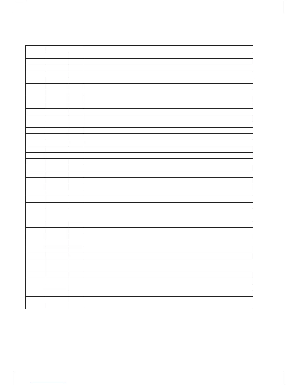
Pin No.
41
42
43
44
45
46
47
48
49
50
51
52
53
54
55
56
57
58
59
60
61
62
63
64
65
66
67
68
69
70
71
72
73, 74
75
76
77
78
79
80
I/O
I
I
I
O
—
I
—
O
I
I
I
—
I
O
I
O
—
—
—
O
O
O
O
O
I
I
O
—
—
O
I
O
—
O
I
O
—
I
Description
Tracking error signal input
Center point servo analog input
RF signal input
TEST terminal (not used)
Analog ground terminal
Constant current input for OP amplifier
Analog power supply
EFM full-swing output (L = Vss, H = VDD)
Asymmetry comparate voltage input
Asymmetry circuit constant current input
EFM signal input
Analog ground terminal
VCO1 control voltage input for multiplication
Filter output (slave = digital PLL) for master PLL
Filter input for master PLL
Charge pump output for master PLL
Analog power supply
Ground terminal
Power supply
Digital-Out output terminal
D/A interface. LR clock output. f = Fs
D/A interface. Serial data output. (2’s complement, MSB first)
D/A interface. Bit clock output
“H” output when playback disc has emphasis. “L” output when playback disc has no emphasis. (Not used)
Oscillation circuit power supply
Crystal oscillation circuit input terminal When master clock is input from external source it is input from
this terminal
Crystal oscillation circuit output terminal (not used)
Oscillation circuit ground
Analog power supply
Analog output L-CH
Analog input L-CH
LPF output L-CH
Analog ground terminal
LPF output R-CH
Analog input R-CH
Analog output R-CH
Analog power supply
Not used in the HCD-MD555 (open)
Pin Name
TE
CE
RFDC
ADIO
AVSS0
IGEN
AVDD0
ASYO
ASYI
BIAS
RFAC
AVSS3
CLTV
FILO
FILI
PCO
AVDD3
VSS
VDD
DOUT
LRCK
PCMD
BCK
EMPH
XVDD
XTAI
XTAO
XVSS
AVDD1
AOUT1
A IN1
L OUT1
AVSS1,
AVSS2
L OUT2
A IN2
A OUT2
AVDD2
RMUT
LMUT