— 120 —
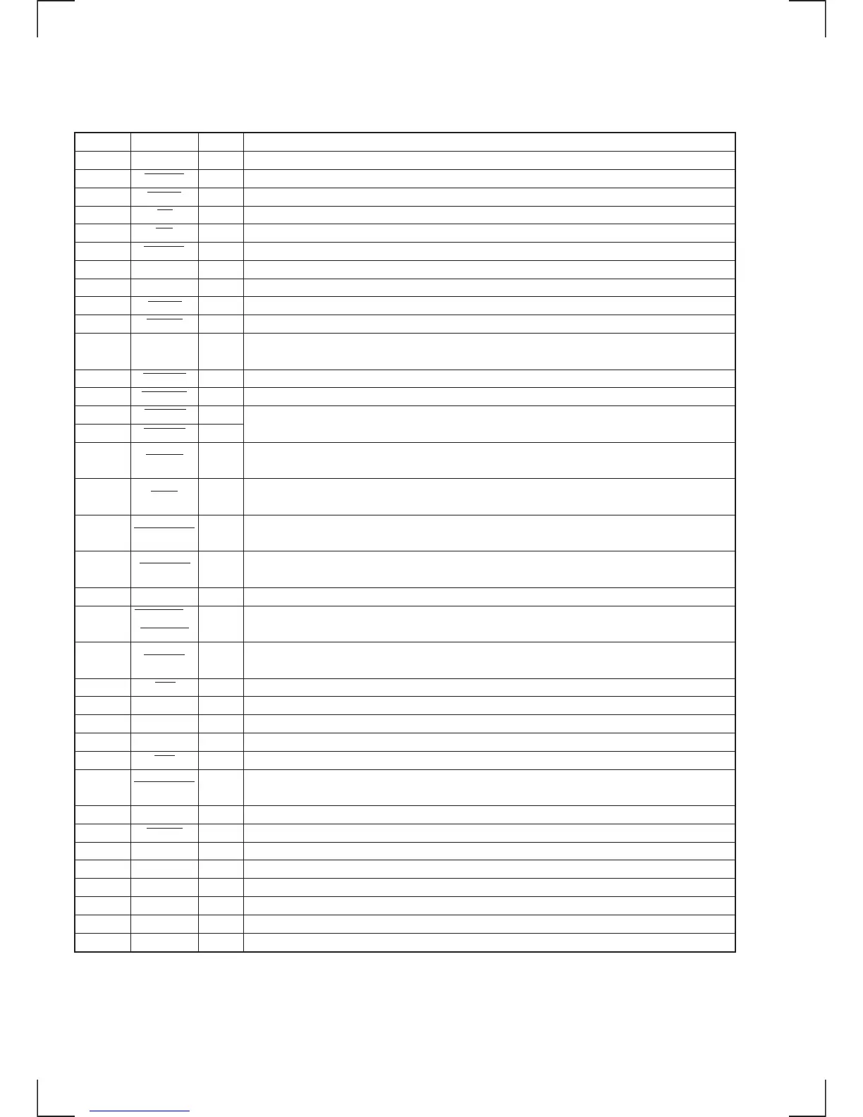
Pin No.
1, 2
3
4
5
6
7
8
9
10
11
12, 13
14
15
16
17
18
19
20
21
22
23 to 25
26
27
28
29
30
31
32
33 to 35
36
37
38
39
40
41
42
I/O
O
O
O
O
O
O
O
—
O
O
O
O
O
O
O
I
I
I
I
I
I
I
I
O
O
O
O
I
I/O
O
—
O
I
—
O
I
Description
Not used in this set (open)
Serial latch pulse signal output to LED driver. Not used in this set (open)
Chip select signal output to display devices. Not used in this set (open)
Output enable signal output to static RAM (IC302). “L”: active
Write enable signal output to static RAM (IC302). “L”: active
Reset signal output to display devices. Not used in this set (open)
Not used in this set (open)
Power supply terminal (+5 V)
Reset signal output to CD section. “L”: reset
Power ON/OFF control signal output to the main power (+5 V) of CD section. “L”: power ON
Not used in this set (open)
Control signal output to the CD loading motor (M702)
Control signal output to the CD loading motor (M702)
Control signal output to the CD clamp motor (M701)
Input signal from the tray OPEN/CLOSE detect switch (S708) of the CD mechanism deck.
“H”: tray is closed, “L”: tray is open
Input signal from the tray OPEN/CLOSE detect switch (S704) of the CD mechanism deck section.
“H”: tray is open, “L”: tray is close
Input signal from the detection switch (S701 (MID OUT)) of the CD mechanism deck.
“L”: When the sub tray is loaded into the stocker
Input signal from the detection switch (S703 (MID IN)) of the CD mechanism deck.
“L”: During the moment when the sub tray moves away from the tray until it is loaded to the stocker
TEST input terminal (fixed at “L” in this set)
Input signal from the roatery encoder (S707) of the CD mechanism deck.
Input signal from the detection switch (S705 (INIT)) of the CD mechanism deck.
“L”: When the tray arrives at the playback position. “H”: In others modes
Input signal for setting the test mode of the CD section. Usually fixed at “H”. (“L”: test mode)
Analog mute control signal output. Not used in this set (open)
Serial data output to CXD2587 (IC101) of the CD section
Clock signal output for serial data transfer to CXD2587 (IC101) of the CD section
Serial latch pulse signal output to CXD2587 (IC101) of the CD section
Input signal from the detection switch (S702 (LID)) of the tray OPEN/CLOSE from the CD mechanism deck.
“L”: open, “H”: close (during playback, etc.)
Not used in this set (close)
I2 bus busy output
Power supply terminal (+5 V)
Main system clock output (12.5 MHz)
Main system clock input (12.5 MHz)
Ground terminal
Not used in this set (open)
Sub system clock input. Not used in this set (fixed at “L”)
Pin Name
—
LEDLAT
DRVCS
RE
WE
DRVRST
—
VDD
BDRST
BDPWR
DRV DAT,
DRV CLK
LOD POS
LOD NEG
CLP POS
CLP NEG
OUTSW
INSW
MIDOUT SW
MIDIN SW
TEST
ENCODE0 to
ENCODE2
INIT SW
ADJ
AMUTE
DATA
CLK
XLT
LID OUT SW
—
12CBSY
VDD
X2
X1
VSS
—
XT1
• IC300 CD MECHANISM CONTROLLER (µPD784215AYFGF-501-3BA) (MAIN BOARD)