— 122 —
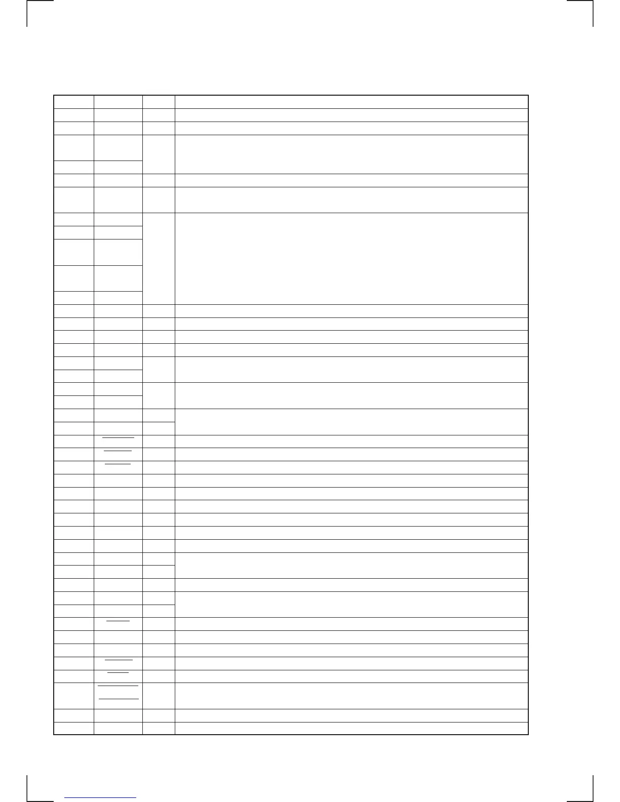
Pin No.
1 to 5
6
7
8
9
10 to 13
14
15
16
17
18
19
20
21
22
23
24
25
26
27
28
29
30
31
32
33
34
35
36
37
38
39
40
41
42
43
44
45
46
47
48
49
50
I/O
O
O
O
—
I
O
O
O
O
—
I
I
O
O
O
O
O
I
O
—
I
O
—
I
O
I
O
O
O
I
I
O
O
Description
Not used in this set (TP501 ~ TP505)
CD = H
LED control signal output
Power supply terminal
Fixed at “H”
EWS control signal output
OK = H. NG = L
MONO = H. STEREO = L
Not used in this set
Test terminal
Volume encoder input
Multi jog encoder input
Not used in this set
Mute signal output to tuner
Stereo signal output to tuner
Tuning signal output to tuner
Enable signal output to tuner
Data output to tuner
Data input for tuner
Clock output to tuner
Not used in this set
Power supply terminal
External crystal is connected to this terminal
Ground terminal
External crystal is connected to this terminal
Reset input
Clock output
Data output
AC cutting signal output
Remote control
Y bus clock input
Y bus clock output
Y bus busy signal output
Pin Name
—
OPT SEL CD
STANDBY
LED
TIMER LED
VDD
SPEC1 to
SPEC4
EWS-OUT
EWS-IN
EWS-
STANDBY
EWS-
WARNING
EWS-TEST
IF-NG
AM-MONO
—
TEST
ENC-VOLA
ENC-VOLB
ENC-JOGA
ENC-JOGB
—
—
ST-MUTE
STEREO
TUNED
ST-CE
ST-DOUT
ST-DIN
ST-CLK
—
VDD
X2
X1
VSS
XT2
XT1
RESET
RDS-CLK
RDS-DATA
AC-CUT
SIRCS
PC-PW REQ
YBUSCLKI
YBUSCLKO
YBUSBUSY
• IC500 SYSTEM CONTROL (µPD784215YGF-505-3BA) (MAIN BOARD)