MHC-V83D
28
Sony CONFIDENTIAL
For Authorized Servicer
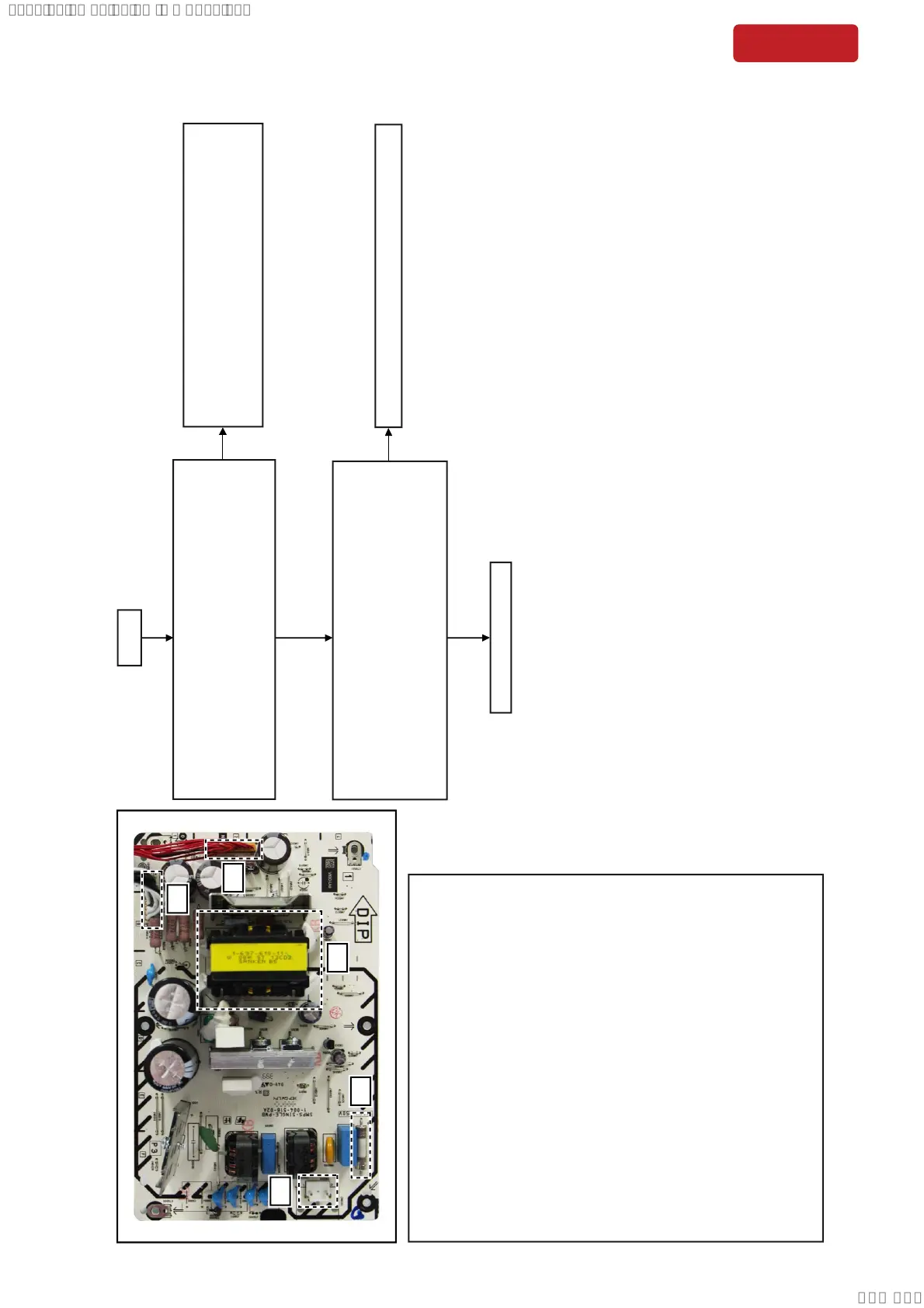
The Output from SMPS board is checked.
Is following power voltage up to standard?
Standby Demo mode Power On
NO6500 Pin1, 4, 5
NO6501 Pin6, 7, 8, 9
AC IN
Yes
No
Yes
END
No
Check whether the state of the Cable and Outlet are
normal. If there are no problems, check circumference
circuit for Main ON on Output of the Motherboard mount
side.
Replaces SMPS board if it is not up to standard.
The Power Control signal to SMPS board is checked.
Is following power voltage OK?
Main ON Standby Demo mode Power On
NO6500 Pin9 Low (0V) Hi (3.3V) Hi (3.3V)
17.4V±5%
17.4V±5%
58.5V±5% 58.5V±5%
17.4V±5%
58.5V±5%
(1) AC input
(2) Fuse
(3) MAIN power transformer
(4) NO6500 connector
Pin 1: Audio (+17V)
Pin 3: Audio (GND)
Pin 4: LED (+17V)
Pin 5: LED (+17V)
Pin 6: LED (GND)
Pin 7: LED (GND)
Pin 8: AC DET
Pin 9: Main ON
Pin 10: Network ON
Pin 11: Latch ON
Pin 12: Low/ High AC
(5) NO6501 connector
Pin 1: PGND
Pin 3: PGND
Pin 4: PGND
Pin 5: PGND
Pin 6: PVDD (DC+58.5V)
Pin 7: PVDD (DC+58.5V)
Pin 8: PVDD (DC+58.5V)
Pin 9: PVDD (DC+58.5V)
(1)
(2)
(3)
(5)
(4)
SECTION 5
TROUBLESHOOTING
SMPS Board Diagnosis Flow
SYSSET
2020/06/2222:32:42(GMT+09:00)

 Loading...