HT-CT800
22
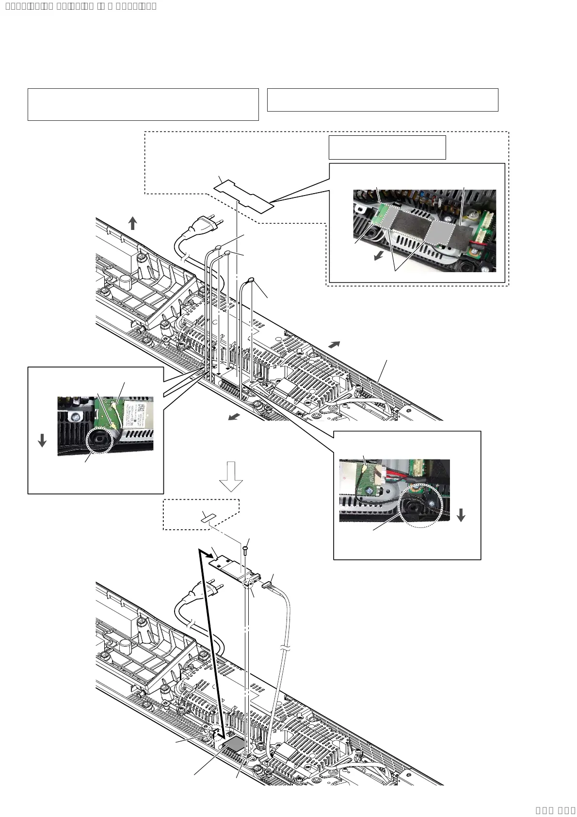
2-17. WLAN/BT COMBO CARD (WIFI1)
XXX XX: X-XXXXX
X-XXX-XXX-XX
1 cushion (WIFI label)
bottom cabinet block
2 connector (No. 3)
[gray]
2 connector (No. 2)
[white]
[white]: No. 2
Pass the coaxial harness
across the front side of
the screw hole.
[gray]: No. 3
[black]: No. 1
Pass the coaxial harness
across the rear side of
the screw hole.
:LUHVHWWLQJ
:LUHVHWWLQJ
2 connector (No. 1)
[black]
rear side
top side
front
side
front side
front side
3 screw
(BVTP3 u 8)
6 CNC label (AR2)
5 MB-1612 board
cable connector
4 claw
rib
groove
7 WLAN/BT combo card (WIFI1)
Note 4:
When installing the WLAN/BT combo card,
align the rib and groove.
radiation sheet
3DVWLQJSRVLWLRQRIWKHFXVKLRQ:,),ODEHO
guide line
guide line
Pressing the adhesive area.
cushion (WIFI label)
front side
Note 3:
This part is deleted from
the midway of production.
$5
Note 1: When the WLAN/BT combo card (Ref. No. WIFI1) is re-
placed, refer to “NOTE OF REPLACING THE MB-1612
BOARD OR WLAN/BT COMBO CARD” on page 5.
Note 2: If the radiation sheet is damaged, be sure to replace them with
new parts.
Ver. 1.3
SYSSET
2019/09/2422:06:08(GMT+09:00)