HT-CT800
24
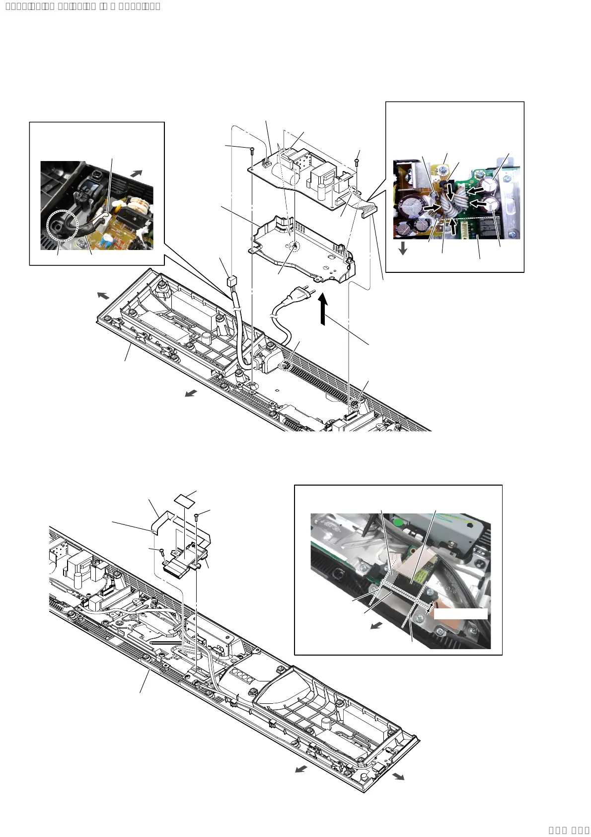
2-20. POWER BOARD
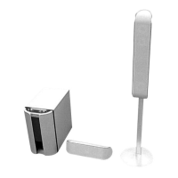
2-21. RF MODULATOR BLOCK
3RZHUFRUGVHWWLQJ
1 power cord
connector
(CN901)
front side
left side
bottom cabinet block
3 three screws
(BVTP3 u 8)
4 Remove the POWER board block
in the direction of the arrow.
5 claw
6 bottom
insulation
assy
7 POWER board
Note 2:
When installing the POWER board,
align the two ribs and two holes.
2 connector (CN6001)
Note 1:
Before connect this connector,
refer to “CAPACITOR
ELECTRICAL DISCHARGE
PROCESSING” on page 4.
3 screw
(BVTP3 u 8)
rib
rib
hole
hole
rear side
[white] : US, CND
[blue] : Except US, CND
power cord
screw hole
:LUHVHWWLQJ
POWER board
guide
line
C6050
C977
C6068
C976
front side
Note 3:
The wire must not touch the
screw boss and four capacitors
(C976, C977, C6050, C6068).
MB-1612 board
screw boss
3 two screws
(BVTP3 u 8)
front side
right side
bottom cabinet block
1 cushion (WS label)
3 screw
(BVTP3 u 8)
2 FFC 24P
(CN701)
The opposite side
is terminal side.
4 RF modulator block
3DVWLQJSRVLWLRQRIWKHFXVKLRQ:6ODEHO
Pressing the adhesive area.
guide line
overlap: 1 mm
cushion (CL3)
guide line
cushion (WS label)
front side
SYSSET
2019/09/2422:06:08(GMT+09:00)