HT-CT800
28
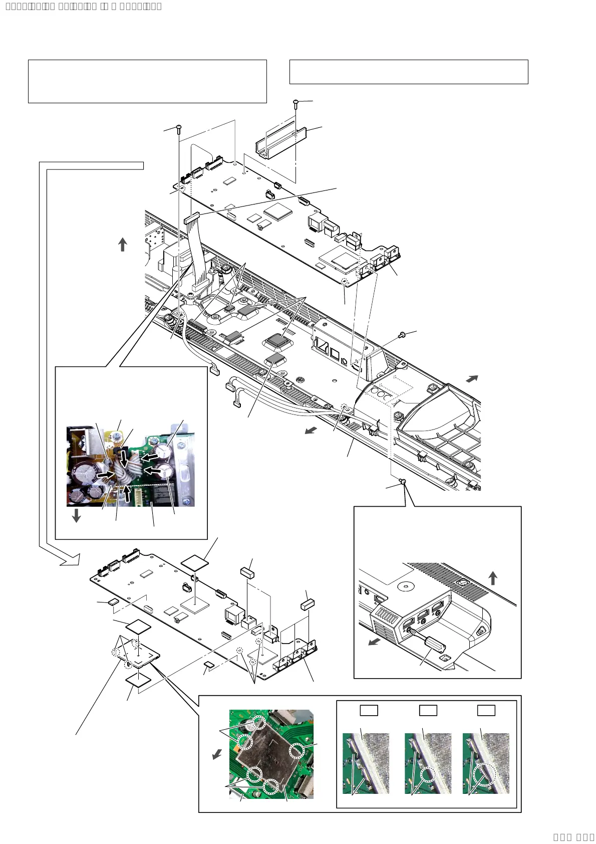
2-25. MB-1612 BOARD
Note 5:
Use a short screwdriver.
If a short screwdriver is not available,
refer to “2-26. BOTTOM CHASSIS
BLOCK” and remove the entire bottom
chassis block.
short screwdriver
2 three screws
(B3 u 5)
3 two screws
(BVTP3 u 8)
2 screw
(B3 u 5)
front side
rear side
top side
bottom cabinet block
rear side
bottom side
qa three
gaskets (SL)
qa two gaskets (SL)
6 radiation
sheet
0 radio wave
absorption
sheet
three legs
qs MB-1612 board
MB-1612 board
8 radiation sheet
7 radiation sheet
8 radiation sheet
radiation
sheet
radiation
sheet
radiation sheet
hole
hole
rib
rib
5 MB-1612 board block
Note 4:
When installing the MB-1612
board block, align the two ribs
and two holes.
9 shield (HDMI)
Note 7:
When installing the shield
(HDMI), align the three legs
and three holes.
shield (HDMI)
shield (HDMI)
shield (HDMI) shield (HDMI)
clip
clip
clip
clip
4 AMP heat sink
Note 3:
When you install the AMP heat sink,
spread the compound referring to
“SPREADING OF COMPOUND”
on page 8.
3 two screws
(BVTP3 u 8)
1 connector (CN6001)
Note 6:
Before connect this connector,
refer to “CAPACITOR
ELECTRICAL DISCHARGE
PROCESSING” on page 4.
:LUHVHWWLQJ
+RZWRLQVWDOOWKHVKLHOG+'0,
POWER board
guide
line
C6050
C977
C6068
C976
front side
three holes
OK NG NG
clip clip
Note 8:
The wire must not touch the screw
boss and four capacitors (C976,
C977, C6050, C6068).
front
side
MB-1612 board
screw boss
Note 1: When the MB-1612 BOARD is replaced, refer to “NOTE
OF REPLACING THE MB-1612 BOARD OR WLAN/BT
COMBO CARD” on page 5, “BOND FIXED POSITION OF
ELECTRICAL PARTS” on page 8.
Note 2: If the radiation sheet is damaged, be sure to replace them with
new parts.
SYSSET
2019/09/2422:06:08(GMT+09:00)