HT-CT800
23
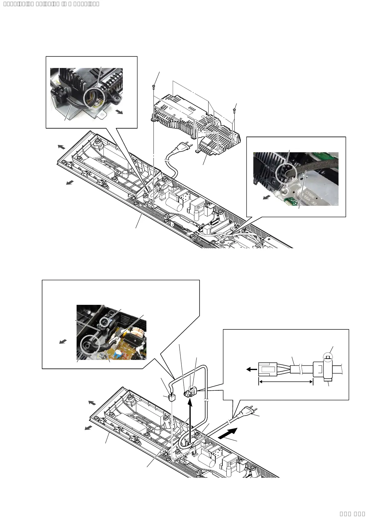
2-18. INSULATION TOP ASSY
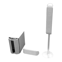
2-19. POWER CORD (AC1)
1 four screws
(BVTP3 u 8)
2 insulation top assy
1 five screws
(BVTP3 u 8)
:LUHVHWWLQJ
:LUHVHWWLQJ
power cord
front side
left side
bottom cabinet block
slot
WLAN/BT combo card cable
slot
front side
front side
3RZHUFRUGEORFNVHWWLQJ
hole
2 Lift up the cord bushing (FBS001)
in the direction of the arrow.
3 Draw out the power cord
block from the hole.
6 power cord
(AC1)
5 cord bushing
(FBS001)
4 Unlock.
power cord
(AC1)
cord bushing
(FBS001)
lock side
85 +0, -5 mm
to
POWER
board
lock side
[white] : US, CND
[blue] : Except US, CND
power cord
cord bushing
(FBS001)
front side
left side
bottom cabinet block
,QVWDOODWLRQSRVLWLRQRIWKHFRUGEXVKLQJ)%6
Note:
When installing the power cord block, check the direction and
position of claw of the cord bushing (FBS001) and install correctly.
front side
1 power cord connector (CN901)
screw hole
claw
side
SYSSET
2019/09/2422:06:08(GMT+09:00)