HT-CT800
29
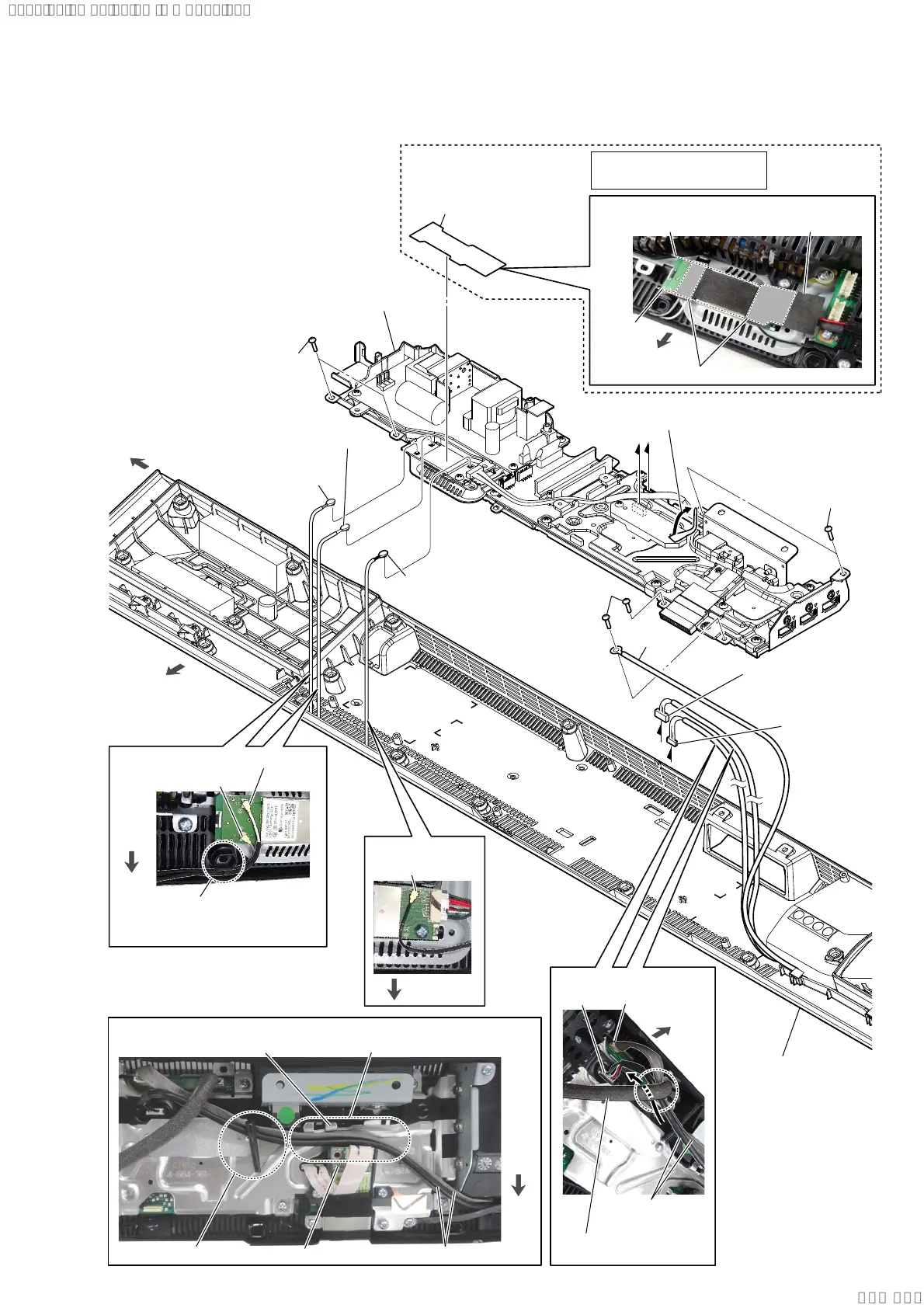
2-26. BOTTOM CHASSIS BLOCK
A
B
B
A
1 cushion (WIFI label)
2 BTW (WIFI-1) board cable
connector (No. 3) [gray]
2 BTW (WIFI-2) board cable
connector (No. 2) [white]
2 BTW (BT) board
cable connector
(No. 1) [black]
3 Remove the two USB-CHUKEI board
cables from the wiring stopper.
4 USB-CHUKEI board
cable connector
(CN501)
5 USB-CHUKEI
board cable
connector
(CN5004)
7 wire
8 bottom chassis block
6 two screws
(BVTP3 u 8)
6 two screws
(BVTP3 u 8)
6 two screws
(BVTP3 u 8)
front side
left side
bottom cabinet block
front side
:LUHVHWWLQJ
3DVWLQJSRVLWLRQRIWKHFXVKLRQ:,),ODEHO
guide line
guide line
Pressing the adhesive area.
cushion (WIFI label)
[white]: No. 2
Pass the coaxial harness
across the front side of
the screw hole.
[gray]: No. 3
[black]: No. 1
:LUHVHWWLQJ
:LUHVHWWLQJ
front
side
USB-CHUKEI board cable
wiring stopper
Pass the USB-CHUKEI board cable between
the RF modulator and shield (main).
shield (main)
RF modulator
USB-CHUKEI
board cable
CN501
WLAN/BT combo
card cable
rear side
:LUHVHWWLQJ
CN5004
front side
front
side
Note:
This part is deleted from
the midway of production.
Ver. 1.3
SYSSET
2019/09/2422:06:08(GMT+09:00)