5
STR-DA3300ES/DG1100
6-70. Schematic Diagram – CIS Board
(DA3300ES: US and Canadian models) – ..................... 97
6-71. Printed Wiring Board – DISPLAY Board – ................... 98
6-72. Schematic Diagram – DISPLAY Board – ...................... 99
6-73. Printed Wiring Boards – PANEL Section –.................... 100
6-74. Schematic Diagram – PANEL Section – ........................ 101
6-75. Printed Wiring Board – DC-DC Board – ....................... 102
6-76. Schematic Diagram – DC-DC Board – .......................... 103
6-77. Printed Wiring Board – AC Board –............................... 104
6-78. Schematic Diagram – AC Board – ................................. 105
7. EXPLODED VIEWS
7-1. Case Section ................................................................... 146
7-2. DISPLAY Board Section................................................ 147
7-3. Front Panel Section ........................................................ 148
7-4. AC/DC-DC Boards Section............................................ 149
7-5. D_AUDIO/D_VIDEO Boards Section ........................... 150
7-6. A_VIDEO Board Section ............................................... 151
7-7. Heat Sink Section ........................................................... 152
7-8. MAIN Board Section...................................................... 153
8. ELECTRICAL PARTS LIST............................... 154
SECTION 1
SERVICING NOTES
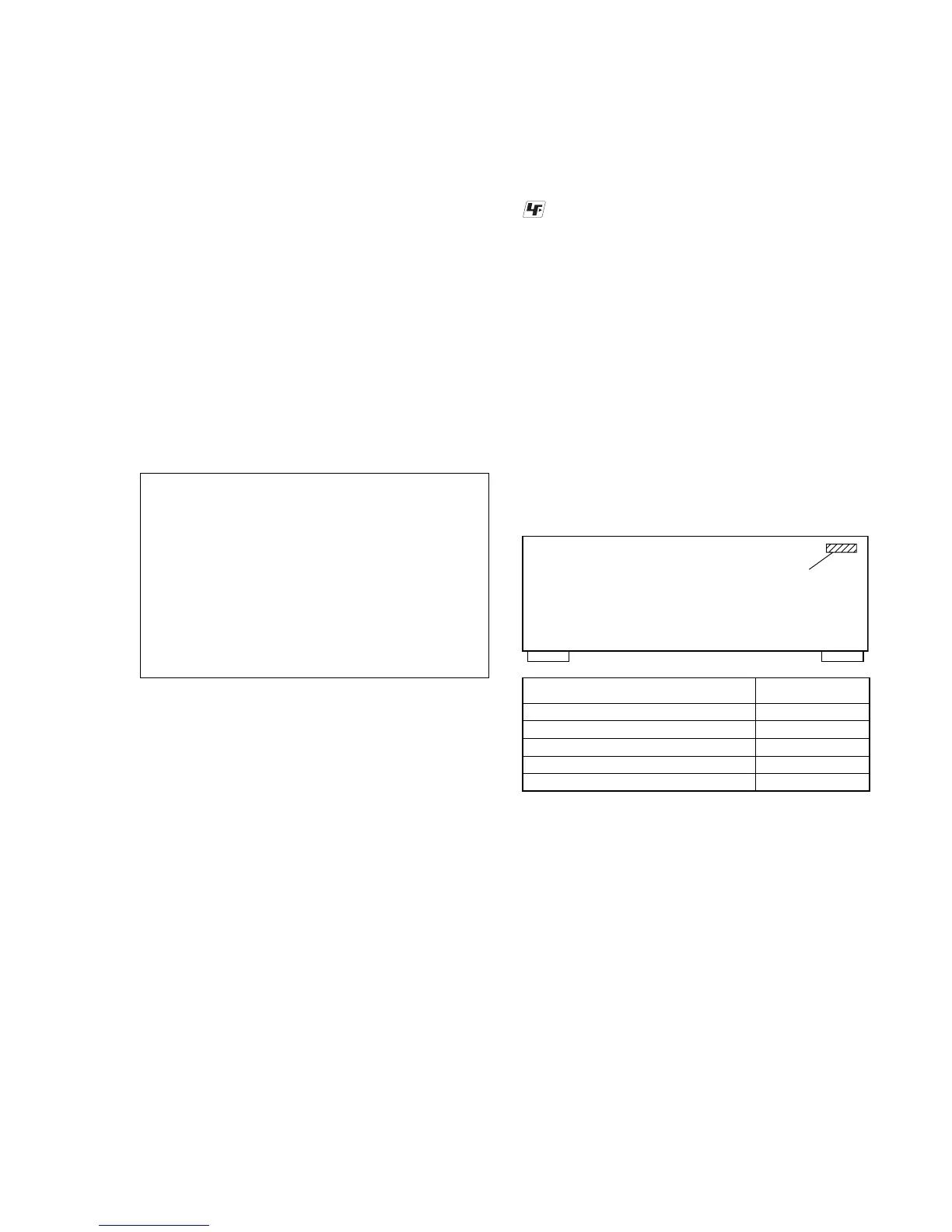
UNLEADED SOLDER
Boards requiring use of unleaded solder are printed with the lead-
free mark (LF) indicating the solder contains no lead.
(Caution: Some printed circuit boards may not come printed with
the lead free mark due to their particular size)
: LEAD FREE MARK
Unleaded solder has the following characteristics.
• Unleaded solder melts at a temperature about 40 °C higher
than ordinary solder.
Ordinary soldering irons can be used but the iron tip has to be
applied to the solder joint for a slightly longer time.
Soldering irons using a temperature regulator should be set to
about 350 °C.
Caution: The printed pattern (copper foil) may peel away if
the heated tip is applied for too long, so be careful!
• Strong viscosity
Unleaded solder is more viscou-s (sticky, less prone to flow)
than ordinary solder so use caution not to let solder bridges
occur such as on IC pins, etc.
• Usable with ordinary solder
It is best to use only unleaded solder but unleaded solder may
also be added to ordinary solder.
• MODEL IDENTIFICATION
Model PART No.
DA3300ES: AEP model 3-113-925-0[]
DA3300ES: UK model 3-113-925-1[]
DA3300ES: US and Canadian models 3-113-925-2[]
DG1100 3-113-925-3[]
DA3300ES: Russian and Ukrainian models 3-113-925-6[]
NOTE OF REPLACING THE IC3511 AND IC3513 ON
THE D_VIDEO BOARD
IC3511 and IC3513 on the D_VIDEO board cannot exchange with
single. When IC3511 and IC3513 on the D_VIDEO board are
damaged, exchange the entire mounted board.
NOTE OF REPLACING THE IC3601 ON THE
D_VIDEO BOARD
Replacement of IC3601 on the D_VIDEO board used in this set
requires a special tool.
Ver. 1.2
Note: Refer to SUPPLEMENT-1 for the A_VIDEO and AC boards
of printed wiring boards, schematic diagrams and electrical
parts list of DA3300ES: AEP, Russian, Ukrainian and UK
models.
Refer to SUPPLEMENT-1/SUPPLEMENT-2 for the MAIN
board of printed wiring board, schematic diagrams and
electrical parts list of DA3300ES: AEP and UK models.
Refer to SUPPLEMENT-2 for the MAIN and TUNER boards
of printed wiring boards, schematic diagrams and electrical
parts list of DA3300ES: Russian and Ukrainian models.
When repairing the set of DA3300ES: US, Canadian, AEP
and UK models/DG1100, refer to either of original service
manual/SUPPLEMENT-1/SUPPLEMENT-2 according to the
set.