Installation and Reference Manual
Technical Data
330 Installation and Re
ference Manual v3.2/0410/6
10 Control – B Pair 10
5 Indicate – A Twisted 5
12 Indicate – B Pair 12
6 SE-Timing – A Twisted 6
13 SE-Timing B Pair 13
8 Ground ----- 8
End A hood is connected to the Screened Cable Drain Wire.
End B is not connected to the screen in any way
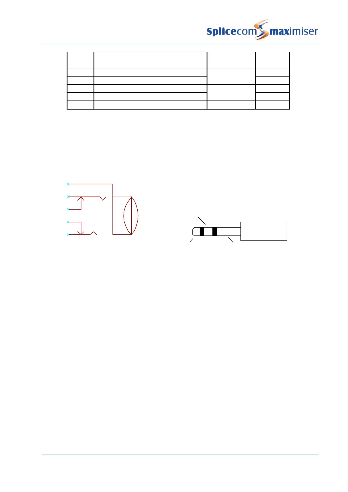
External devices may be switched by the relay outputs provided by the 3.5mm stereo jack sockets.
Socket Plug
Connected to unit chassis
3 Not connected
4 Not connected
The shield connector of the mating plug is connected to the unit chassis.
The on board relays are solid state optically isolated devices that can connect plug contacts “channel A” to
“channel B”. Their characteristics are as follows:
Switching ability = a.c. or d.c signals of either polarity.
Absolute Maximum Voltage = 60V peak. Beyond this, damage will occur.
Recommended Maximum Voltage = 48V.
Maximum relay on impedance = 15 Ohms.
Minimum relay off impedance = 500MOhms.
Recommended Maximum current = 140mA.
Current Limit = 300mA.