28
7.7 TRIGGER
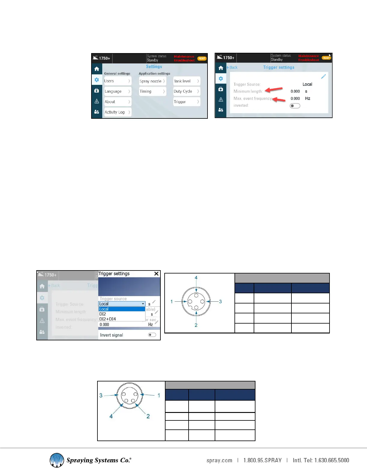
If you have an external trigger source, select the correct and corresponding opon for your external trigger from the
drop down list. Toggling the “Inverted” opon to the On posion will allow the use of a trigger that sends a signal when
o rather than when on.
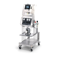
TRIGGER SETTINGS
• Minimum length: Filters out a trigger signal that is less than the specied me. This seng can only be used while
there is a start delay.
• Max. event frequency: When the max trigger frequency is exceeded, the signal is treated as noise and will not give
the controller a trigger signal. A higher max frequency allows for more noise and could cause unnecessary triggers
from a bad signal. Signals that have some noise, but should sll be considered triggers should be accounted for with
this seng.
• Trigger Source:
—Local- Selecng “Local” as a trigger source will place a trigger buon on the home screen that must be pressed
every me the system needs to be triggered.
—DI2- Trigger is acvated via the "Trigger Connecon"
—DI2+DI4 - DI4 is the trigger interlock connecon. This will place the system into standby mode when DI4 is low.
DI2 operates as normal when in run mode.
• Check Trigger On Run: When this opon is acvated if the system goes from standby to run mode the system will
look for a trigger signal and spray when the trigger is high. If this seng is o the system will look for a fresh trigger
signal to resume spraying.
• Trigger Interlock: Controls the state of run/standby. When the signal is low it will put the system in standby mode
and spraying will stop. When the signal is high again it will be put back into run mode.
Trigger sengs
Color Code: Trigger
Pin # Color Descripon
1 Brown +24 VDC
2 white 0VDC
3 Blue 0VDC
4 Black DI2
Trigger Sengs
Male version circles are
lled in.
Color Code: Trigger Interlock
Pin # Color Descripon
1 Brown +24 VDC
2 white DI4
3 Blue 0VDC
4 Black Level Sensor