41
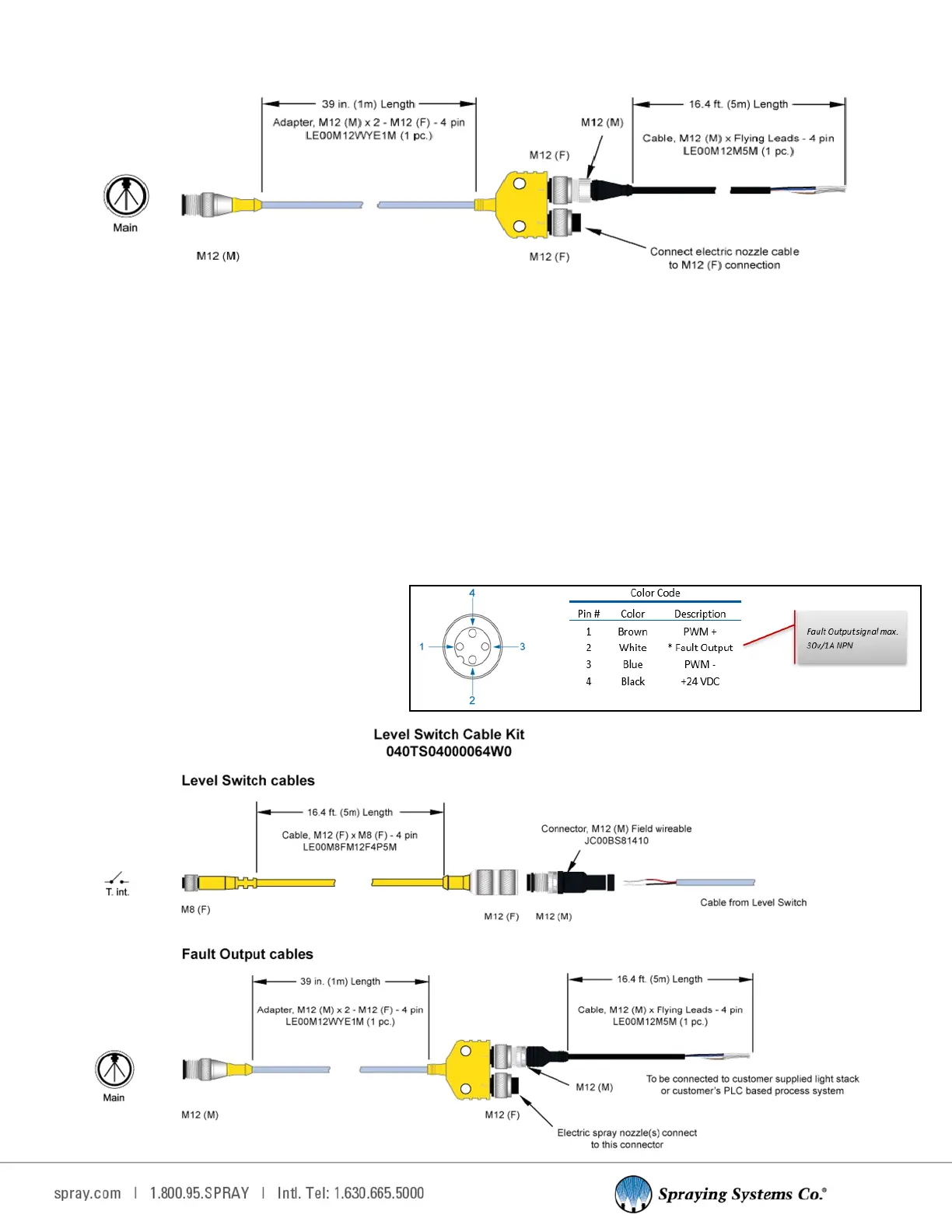
12.13 FAULT OUTPUT CABLE KIT
The 1750+ and 2150+ oer a feature to provide a signal when a fault has occurred during operaon. This is wired as
shown in the table below. To use this feature, you need to have our oponal splier cable kit.
•
Panel connecon: Main and T. int.
•
Kit number: 040TS04000064W0
•
Adapter: Splier- wye, M12, 4 pole, trunk = male M12 1m whip, 2 branches x M12 female coupling nuts, TPU,
parallel wiring. (Part number: LE00M12WYE1M)
•
Cable: Main, M12 (M) x Flying Leads - 16. 4 . [5 m] cord length, bare leads, M12 4 pin (M), 4 wire. (Part number:
LE00M12M5M)
Connects to one connector on splier
The ying leads from cable of the kit are to be connected to the customer’s PLC or warning signal light,
+24VDC. (black and white wires)
•
Open connector on splier
Connect PulsaJet cable; AA250 cable; or
extension cable to this connecon.
Fault Output Signal Kit
040TS04000054W0