27
7.6 DUTY CYCLE
Duty cycle represents the rao of the spraying "on" me to the "o" me, which results in some percentage of the
maximum possible (connuous) ow through the nozzle. The duty cycle sengs allow you to select the source and
enter sensor default values. Selecng 4-20mA signal will allow you to congure your sensor. The other opon is remote
setpoint, which requires a cable to connect to an external PLC. When connected correctly, the Duty Cycle on the
controller display adjusts according to the input signal, 4mA corresponds to 0% duty cycle and 20 mA corresponds to
100% on.
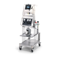
DUTY CYCLE SETTINGS
Select whether the duty cycle source will be local or 4-20mA signal.
• Sensor Value at oset: The minimum value of percent that oset the starng point to control Duty Cycle.
• Sensor Value at 20mA: The maximum value of setpoint for the remote duty cycle to control. Set the value at 20mA
to be 100% or another value depending on your trigger source.
• Sensor Oset: The minimum level of the sensor oset can control usually starng from 0mA or 4mA. Set the sensor
Oset to match the baseline mA value of your sensor (lowest value).
• Filter Time: Used to control interference/noisy signals from sensor.
Assembly Specicaons:
•
Panel connecon: 4-20mA
•
Part number: LE00M8M5M
•
Cable: 16.4 . [5 m] cord
•
Flying Leads
•
Connector – M8 4 pin male
—DO2 represents your spray status in the form of an On/O signal depending on whether the 1750+ is acvely
spraying. This can be used to monitor the acve status externally.
REMOTE SETPOINT (AI2) [0-20MA] DUTY CYCLE
The duty cycle setpoint is mulplied by the value of the input to calculate the actual duty cycle. The following equaon
represents the calculaon made by the 1750+.
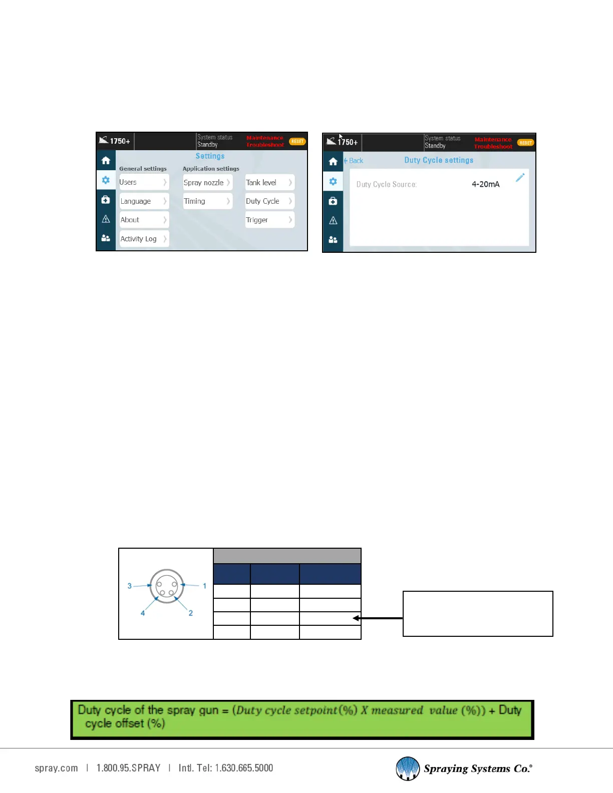
Duty Cycle Sengs
Color Code: Duty Cycle
Pin# Color Descripon
1 Brown +24 VDC
2 White DO2
3 Blue 0 VDC
4 Black 4-20mA
If your 0 VDC is coming from a
power supply outside of our panel
(PLC), connect it to this wire—#3