43
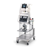
12.16 LEVEL SENSOR INPUT
A level switch (any normally open or normally closed oat switch) can be wired to the system, so when the tank level
drops below a certain level, a fault will be shown on the HMI.
Wire the level sensor/oat switch to the panel ulizing the cable shown below. You will only use the black and blue
wires (dry contacts - polarity not important), carefully cut back and tape the brown and white wires. Run the cable
back to the spray control panel and plug into the port labeled “T. Int.”.
Acvate level sensor opon, go to sengs in the HMI then “Tank level” and turn on.
Specicaons:
•
Part number: LE00M8F5M.
•
Panel connecon: T. int. (Soware - DI2+DI4)
•
Cable: 16.4 . (5 m) cord length
•
Flying leads
•
Connector end - M8 4 pin female
•
Cable, M8 Female, 4 pole, bare leads, 5 meter
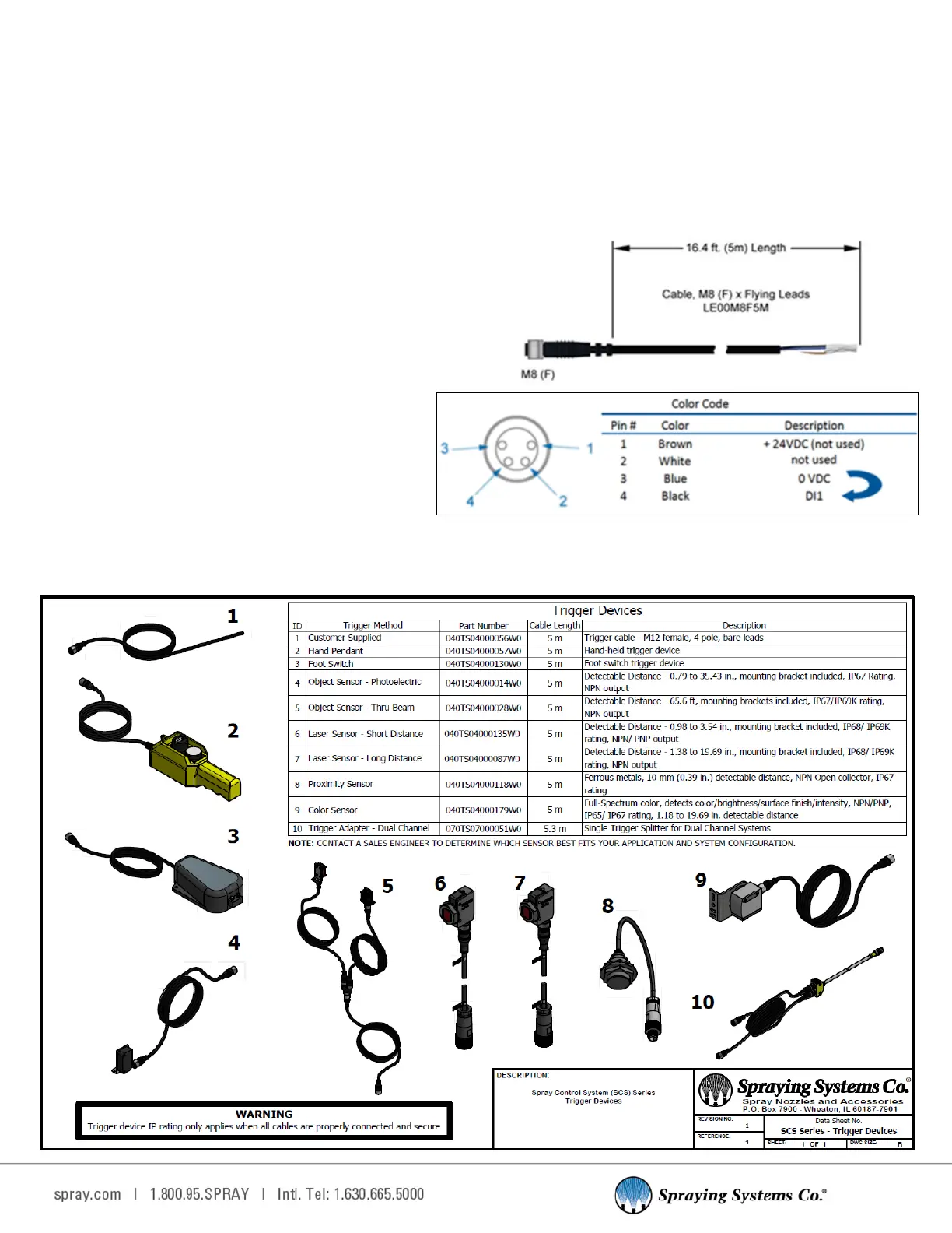
12.17 TRIGGER DEVICES OVERVIEW