42
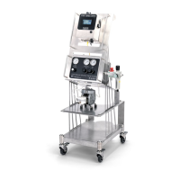
12.14 EXTENSION CABLE
If longer length cables are required, an extension cable is available that can be used to go between the nozzle cable
and the juncon block or the juncon block cable and the system. This cable can also be used to extend the trigger
device cable lengths.
This cable can be used to go between the nozzle cable and the juncon block or the juncon block cable and the
system or extend the trigger device cable lengths. When using to extend electric nozzle cables, connect electric nozzle
cable to M12 (F) connector. When using to extend electric nozzle cables, M12 (M) connects to “Main” connector on
the control panel or juncon block. When using to extend sensor cables, connect M12 (F) connector to “Trig”
connector on the “Trig” Control Panel. When using to extend sensor cables, connect M12 (F) connector from sensor
cable to M12 (M) connector of the extension cable.
Note: Due to voltage drop we recommend keeping the cable length to a reasonable length. Never aempt to chain
more than four (4) cables together. Electric spray nozzle speed and performance will suer.
•
Part number: LEXXSD4FD4M005P
•
Connect to Main or Trig on control panel
•
Cable: 16.4 . [5 m] cord length
•
Connector – M12 4 pin female
•
Connector – M12 4 pin male
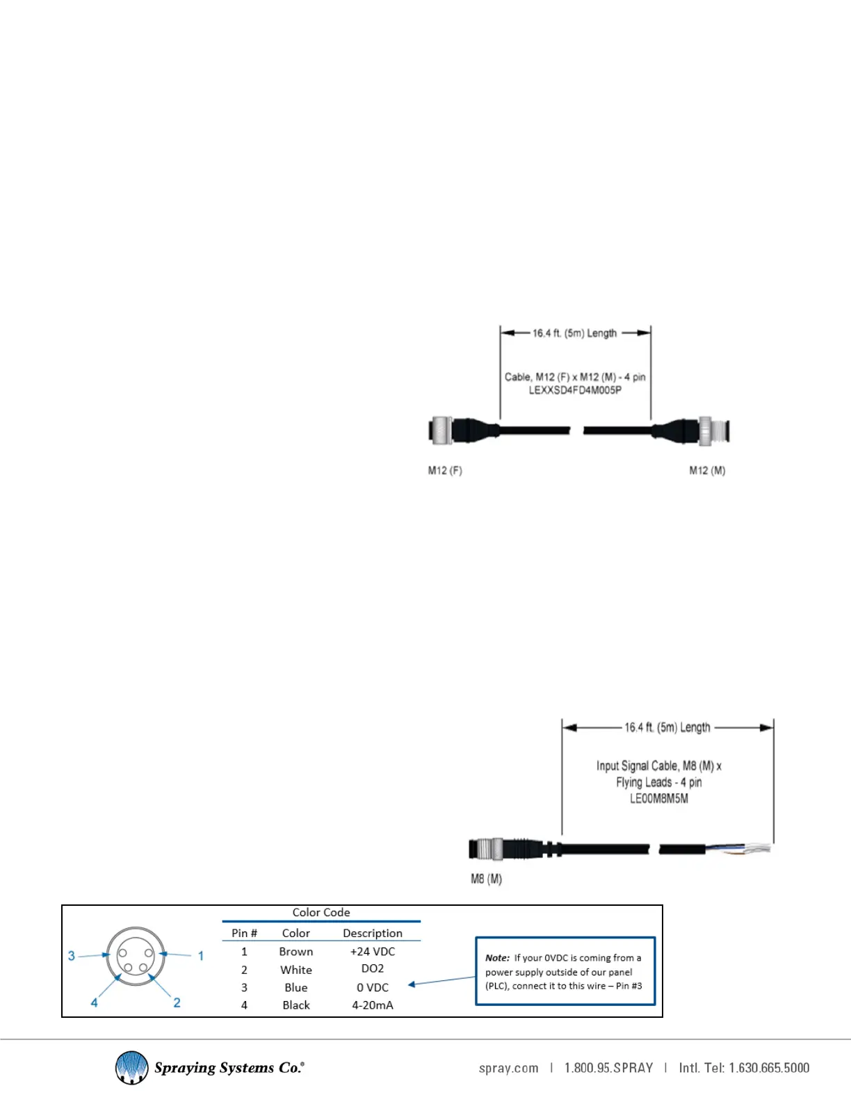
12.15 INPUT SIGNAL
Oponal Input signal oering consists of a cable with connector and ying leads to be connected to the customer's
condioned 4-20 mA signal to remotely control the PWM (Pulse Width Modulaon) feature of the spray control pan-
el. This will allow the duty cycle to adjust according to the input signal. 4mA corresponds to a 0% duty cycle and 20
mA corresponds to a 100% duty cycle.
For the spray indicator digital output (DO2), wire to pins 1 and 2 (brown and white wires). This output is acve only
when the system is triggered, it can be sent to a PLC for spray vericaon.
ASSEMBLY SPECIFICATIONS
•
Panel connecon: 4-20mA
•
Part number: LE00M8M5M
•
Cable: 16.4 . [5 m] cord
•
Flying Leads
•
Connector – M8 4 pin male
•
Connect to “4-20mA” connecon on control panel