7
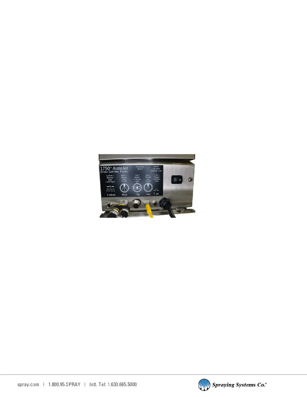
3.3 PLUG AND SPRAY CONNECTIONS
All the connecons are the same as the full system. Located on the boom of the panel the connecons are as follows.
•
Power input connecon, route power cord through oval opening on right-hand side of frame and plug in 120 VAC
outlet rated for at least 5A.
•
4-20 mA - Remote Duty Cycle Input. Analog input is accessible through this connecon.
•
Main - Nozzle Liquid ON/OFF connecon. Use this output for the connecon on all electric spray nozzles and
cylinder air.
•
Trig - Is the input connecon for the system trigger or sensor. Connect cable to Trig connecon that will be used to
start spray sequence. Available triggers are as follows, the one used should be based on the customer’s applicaon.
- Trigger cable (for use with customer-supplied trigger signal)
- Sensors including: object, proximity, laser (short/long), thru-beam, and full spectrum color sensor.
- Hand-held trigger unit
- Foot switch
•
Aux - Nozzle air ON/OFF for fan and atomizing air control.
•
T. int. - Used for the oponal trigger interlock or level switch input. Trigger Interlock controls the state of run/
standby mode.
PLUG AND SPRAY COMPATIBILITY
The 1750+ can be mounted to the universal frame with mobile cart. Plug and Spray provides quick hook up for all
nozzles, an Air Control Package (ACP), triggers, and any other compable SCS Series accessories including a level
switch, an interlock cable, and the remote setpoint cable. Plug into GFCI outlets.
POSITION OR MOUNT THE SYSTEM
Find a convenient locaon for the 1750+ AutoJet
®
Spray Control System within a reasonable distance of your spray
applicaon and easily accessible to a properly grounded power outlet. The unit must be installed when the cord is
connected, the plug can be easily reached and easy to remove from the outlet.
- Determine if the unit will be free-standing or wall mounted.
CONTROL PANEL ONLY VERSION
If you have the Control Panel Only version the unit should be wall mounted.
Install wall anchors that are designed to support at least 25 lbs., according to the anchor manufacturers’ specicaons.
The mounng holes are on 5 7/16” (138 mm) centers and are made for 1/4” (6 mm) screws with 3/8” (10 mm)
diameter screw heads. Secure the Model 1750+ to its selected locaon.