39
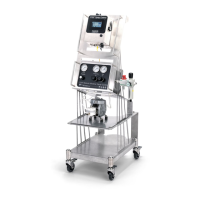
12.8 HAND TRIGGER PENDANT
For manual triggering of the system. The unit oers two switches to independently trigger the system. Cable length
oers exibility in locaon of operaon.
SPECIFICATIONS:
•
Part number: SW001550M12HT
•
2 Switches
1 - On/O selector switch
1 – Pushbuon – momentary on buon
1550, hand trigger pendant, selector switch and buon, M12 female 4 pole, 5
meter cable.
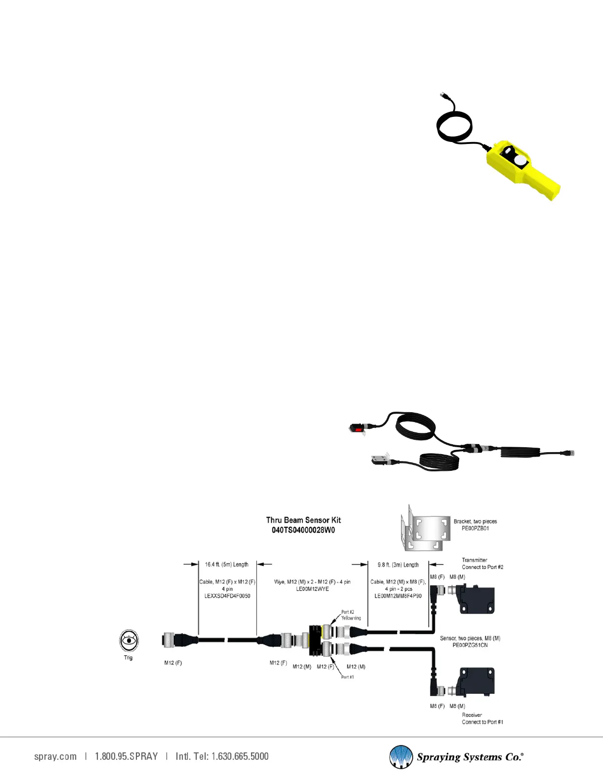
12.9 Thru-Beam Sensor
Infrared - thru beam sensor with cables, wye connector and brackets. To set this up you need to use all three cables
and the splier. The thru beam has a sensor and a receiver. Each gets a cable connecng it to the splier. Then the
splier has a cable to connect it to the system.
The receiver goes to port 1 on the wye splier, and sensor cable goes to port 2. Refer to the manufacturers’ data
sheet for more informaon on seng up the sensor for use.
SPECIFICATIONS:
Photoelectric sensor – Infrared – direct reecon sensor with cable, connector, and bracket.
•
Kit number: 040TS04000028W0
•
NPN – NO + NC
•
65.6 feet [20 m] sensing range
•
Working temperature range = -4°F to 130°F [-20°C to 55°C]
•
IP67; CE rated
•
IP67/IP69K rang, NPN output
ASSEMBLY SPECIFICATIONS:
•
Panel connecon: Trig
•
Cable: 16.4 . [5 m] cord length, Connector – M12 4 pin female