104/317
5 - Peripherals
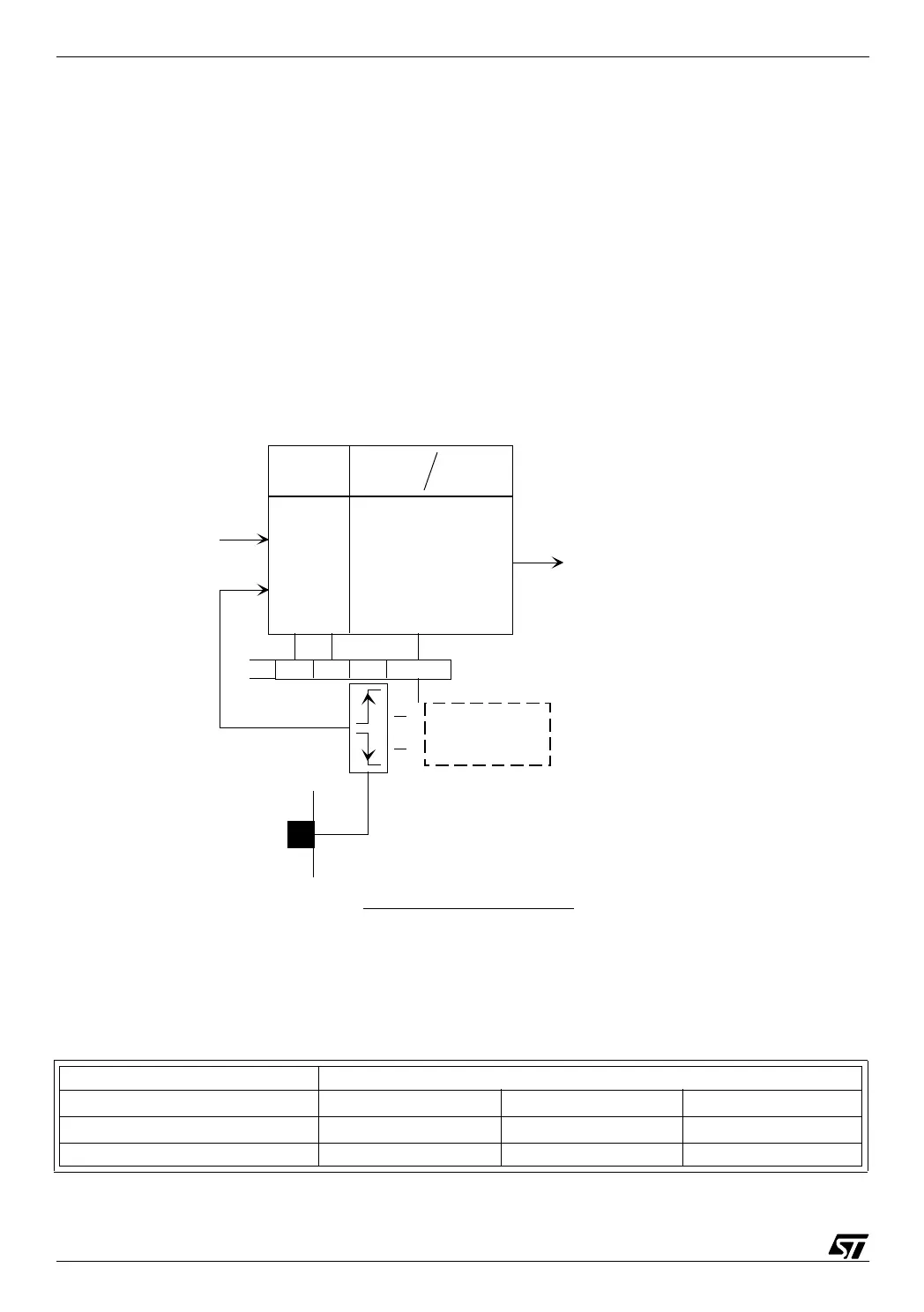
5.5.1 Timer clock
Two clock sources are available for the timer: either the core clock, or an external clock sup-
plied on a pin that takes up one port pin.
When the internal clock is used, the timer is actually fed with the core clock after passing
through a frequency divider that can divide the core clock frequency by 2, 4 or 8. The core fre-
quency is itself derived from the crystal oscillator by dividing it by 2 (normal mode) or a higher
value that depends on the variant of ST7 considered (slow mode), as selected in the miscel-
laneous register (see the beginning of this chapter).
The external clock, when selected, changes one parallel input-output pin into a clock input.
The frequency applied to the pin is directly fed to the timer with no predivision. The external
clock is only available on Timer A on the ST72251 and ST72311.
05-timck
To give an idea of the time resolution of the timer, the following table give the resolutions avail-
able with a 16 MHz crystal for all divider selections:
Timer clock predivisor
Core predivisor 1/2 1/4 1/8
1/2 0.25 0.5 1
1/32 4 8 16
Prescaler
Timer clk
CPU clk
00
01
10
11
1/4
1/2
1/8
External
CC1CC0 EXEDG
1
0
rising or falling
edge selection
External timer
clock pin *
External
timer clock
CPU clock
or
Internal
timer clock
* External clock pins are available
only on timerA :
Pc5fortheST72251
Pf7 for the ST72311
Maximum frequency of
the external clock = 1/4 CPU clock
Timer Clock selection
Timer A contr ol
register 2 (TACR2)