128/317
5 - Peripherals
The CPOL and CPHA bits in the control register allow you to select which clock edge is used
externally as the active one (leading or trailing) and its polarity (low or high level after trans-
mission).
5.8 SERIAL COMMUNICATION INTERFACE
The Serial Communication Interface is perhaps the most classical interface used when two
systems are connected together. This is especially true when a small system is connected to
a PC, either permanently, or temporarily, for instance for calibration, logging or maintenance.
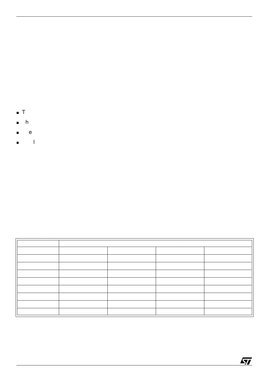
The SCI differs from the SPI in several ways:
The clock is not transmitted along with the data;
The first data bit is preceded by a Start bit;
The first data bit sent is the low-order bit;
The last data bit is followed by a Stop bit.
5.8.1 Bit rate generator
The bit clock is derived from the CPU clock, divided by a user-selectable value. There are two
ways of doing this:
For the most popular bit rates, the Baud Rate Register offers a choice of four prescaler values,
and the output of the prescaler is further divided by two separate divisors that provide the re-
ceive bit rate and the transmit bit rate. The prescaler is driven by the core clock divided by 32.
This gives the following combinations (only the receive bit rate is considered here, because
the transmit bit rate is produced exactly the same way):
For a 8 MHz core clock (16 MHz crystal):
Prescaler value
Divider value 1 3 4 13
1
250000 83333 62500 19231
2
125000 41667 31250 9615
4
62500 20833 15625 4808
8
31250 10417 7813 2404
16
15625 5208 3906 1202
32
7813 2604 1953 601
64
3906 1302 977 300
128
1953 651 488 150