269/317
9 - A Carrier-current System for domestIc Remote Control
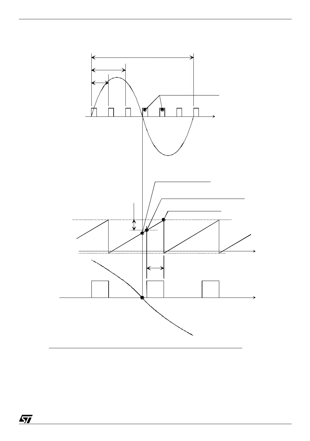
The operation of the PLL is illustrated by the diagram below:
09-pll
9.2.3.3 The Timer B overflow interrupt service routine
This routine has a dual role: it refreshes the display and counts down the time.
Transmission windows
T : 20ms (50Hz)
T/6
T/3
2000
TimerAPeriod
initialized to
6661
FFFCh
1ms
Compare 2 interrupt stops the burst and
restarts the counter
Compare 1 launches the burst (if need be)
Sine wave
Zero
crossing
point
Capture 2 interrupt (desynchronisation
measurement)
Carrier-current system : phase-locked loop of the transmitter
Depending on the difference
found between the Capture 2 timer
value and the Compare 1 registers,
the TimerAPeriod variable (loaded in
the Compare 2 registers) is adjusted
in the PhaseLockedLoop interrupt
routine.
The value of Compare1 registers
is always equal to the contents of
Compare2 registers - 2000