127/317
5-Peripherals
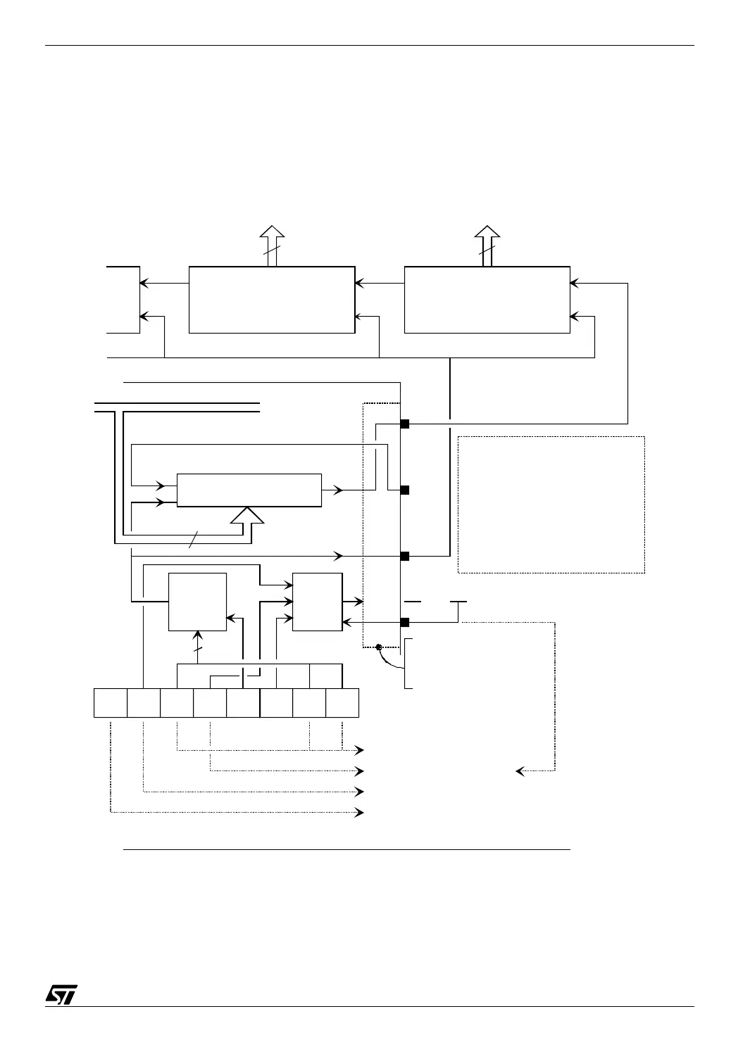
An example of the use of the SPI to send data to a LCD display module is given in the second
application, Chapter 10. The configuration used is shown in the figure below with the appro-
priate values in the registers.
05-app10
8-bit shift register
SPIDR
Internal data bus
MOSI
MISO
SCK
SPI
Clock
Generator
SPIE
0
SPE
1
SPR2
1
MSTR
1
CPOL
0
CPHA
0
SPR1
0
SPR0
0
Max speed (f
cpu
/4)
Permanent master mode
SPI alternate functions connected to pins
No interrupt in this application
SS
Vdd
SPI
State
Control
3
Serial
data out
Serial
data in
External shift registers
Clock
8
Parallel data out
40944094
Expanding the parallel outputs using the SPI and external shift registers
8
8
SPICR
ST72311
I/O or alternate function
circuitry (SPE), master or
slave configuration (MSTR)
SPR0-SPR1-SPR2: Rate selection
SPIE: Interrupt enable
SPE: Output enable
MSTR: Master
CPOL: Clock polarity
CPHA: Clock phase