116/317
5 - Peripherals
05-PWM
The settings for this mode are performed as follows:
Set the TAOC1HR-TAOC1LR pair to the number of ticks corresponding to the duration of
the output pulse (this number depends on the clock frequency), minus 4.
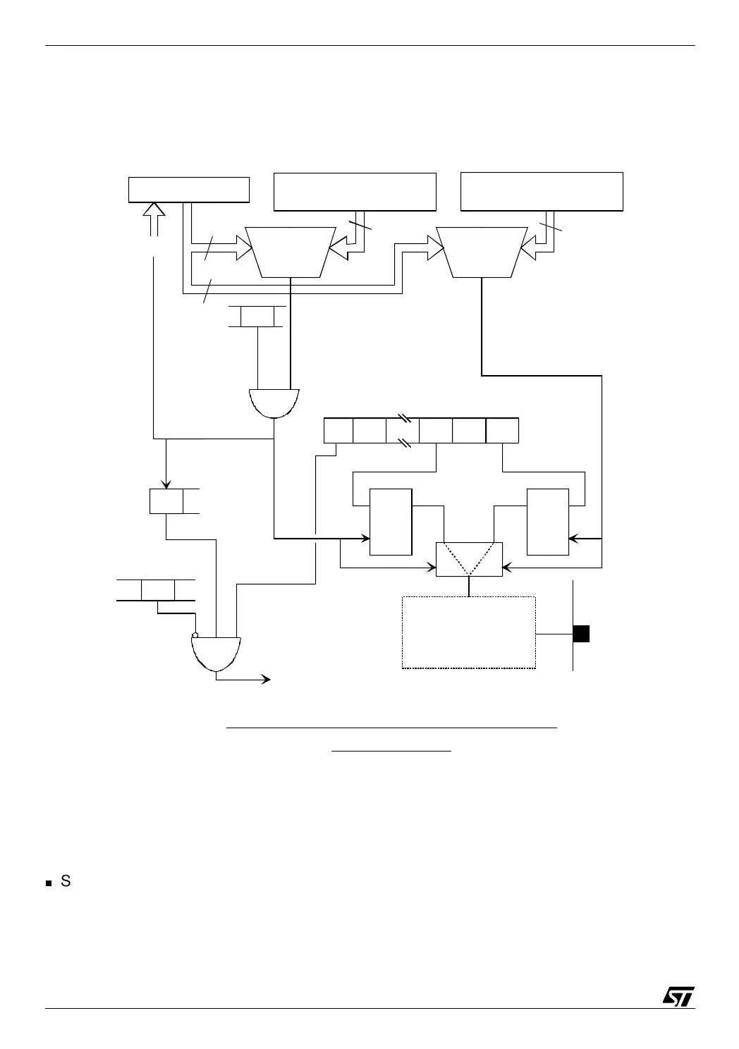
PWM mode and corresponding interrupt mechanism:
diagram for timer A
Interrupt to
the core
Free running counter
16 bit output compare register
TAOC1HR, TAOC1LR
16
16
Compare
loaded with the duration
of the pulse
Timer A control
register 1 (TACR1)
OLVL1OLVL2
Clk
latch
Clk
latch
Configuration of
the output compare pin
(see the output compare
mode diagram)
ICIE
ICF1
I
Condition code
register (CCR)
Timer A status
register (TASR)
Output
compare 1
pin
FFFCh
PWM
Timer A control
register 2
(TACR2)
16 bit output compare register
TAOC2HR, TAOC2LR
loaded with the duration
of the period
Compare
16
16