95/317
5-Peripherals
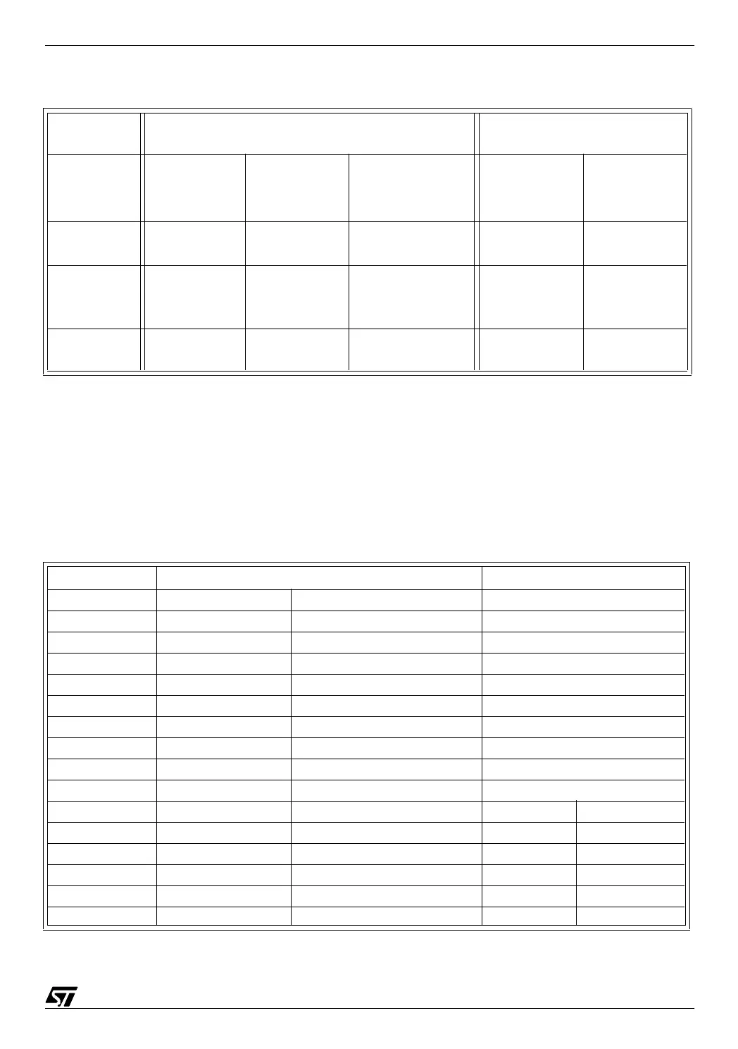
Table 3. ST72251 I/O configuration
In addition, some pins also serve as inputs for other peripherals, or may be held from their
normal output function and be taken as the output pins of some peripherals if those periph-
erals are specially configured to do so by setting a bit in one of their control registers. As an ex-
ample, pin PB0 is also used as the capture input of Timer A, and pin PC1 is the output com-
pare 1 pin of Timer B if the OC1E bit of register TCR2 of this timer is set. The interaction with
the pins and the required precautions are discussed, when needed, in the paragraph related
to the corresponding peripheral.
Table 4. ST72251 I/O alternate functions
Note: All pins of port C have two alternate functions.
Input configuration
(DDR=0)
Output configuration
(DDR=1)
Port
OR = 0 OR = 1
External interrupt
source,
Polarity option bits
OR = 0 OR = 1
Port A:
PA0-PA7
Floating
Floating with
interrupt
EI0
PEI0-PEI1
True open
drain
Reserved
Port B:
PB0-PB7
Floating
Pull-up with
interrupt
EI1
PEI2-PEI3
Open drain Push-pull
Port C:
PC0-PC5
Floating
Pull-up with
interrupt
EI1
PEI2-PEI3
Open drain Push-pull
I/O pin Alternate function 1 Alternate function 2
PA4 SLC (I²C)
PA6 SDA (I²C)
PB0 ICAP1_A (Timer A)
PB1 OCMP1_A (Timer A)
PB2 ICAP2_A (Timer A)
PB3 OCMP2_A (Timer A)
PB4 MOSI (SPI)
PB5 MISO (SPI)
PB6 SCK (SPI)
PB7 SS (SPI)
PC0 ICAP1_B (Timer B) Ain0 (ADC)
PC1 OCMP1_B (Timer B) Ain1 (ADC)
PC2 CLKOUT (Internal clock out) Ain2 (ADC)
PC3 ICAP2_B (Timer B) Ain3 (ADC)
PC4 OCMP2_B (Timer B) Ain4 (ADC)
PC5 EXTCLK_A (Timer A) Ain5 (ADC)