4.5.12. The Standa stages detection
Newest Standa positioners (please check with the manufacturer for the list of exact models) have an option to store settings and
informational parameters in the internal positioner memory. This chip is flashed with correct settings, which allows one to skip optimal
positioner configuration and to start working with the positioner right out of the box. This memory chip also holds user-defined
positioner name (see XiLab tab Positioner name).
When this kind of positioner is connected to the controller (for more information about electrical connection please see example of
motor connection and positioner connector) informational parameters are automatically loaded into the controller memory, see
Positioner specifications. If the EEPROM_PRECEDENCE flag was set, which indicates precedence of settings read from external memory
over the settings saved in the controller flash memory (see About controller), then all controller settings except UART settings and
controller name are also read and applied.
If the EEPROM_PRECEDENCE flag is set then you don't need to check and/or set positioner settings (for example limit switches
orientation and position, nominal current, encoder and magnetic brake parameters, etc). All of this will be done automatically when a
positioner with internal memory chip is connected. However, if this flag is set then settings from positioner memory will be loaded
every time a positioner with memory chip is connected and every time the controller is powered on. That is why if you need to change
some settings you need to clear this flag, change required settings and save them to controller flash memory.
Note. There is a simple rule for this flag preferred state: This flag should be true on early stages of work to embrace
the simplicity of automatic settings. Later, as soon as the will be need for fine tuning the settings, this flag should be
set to false, not forgetting to save this to FRAM.
Note. If a positioner with internal memory is disconnected from the controller no settings are changed.
For developers
Positioner data is stored in DS28EC20 chip connected by 1-wire interface.
Controller periodically sends reset signal to the EEPROM chip during positioner detection. If a response is received, then controller
reads data from the positioner into RAM, applies settings and sets STATE_EEPROM_CONNECTED bit in status structure. In XiLab this is
shown by EEPR indicator in the main window. The EEPROM is then regularly polled. In case connection with EEPROM is lost (no
response to the reset signal) EEPR XiLab indicator is cleared.
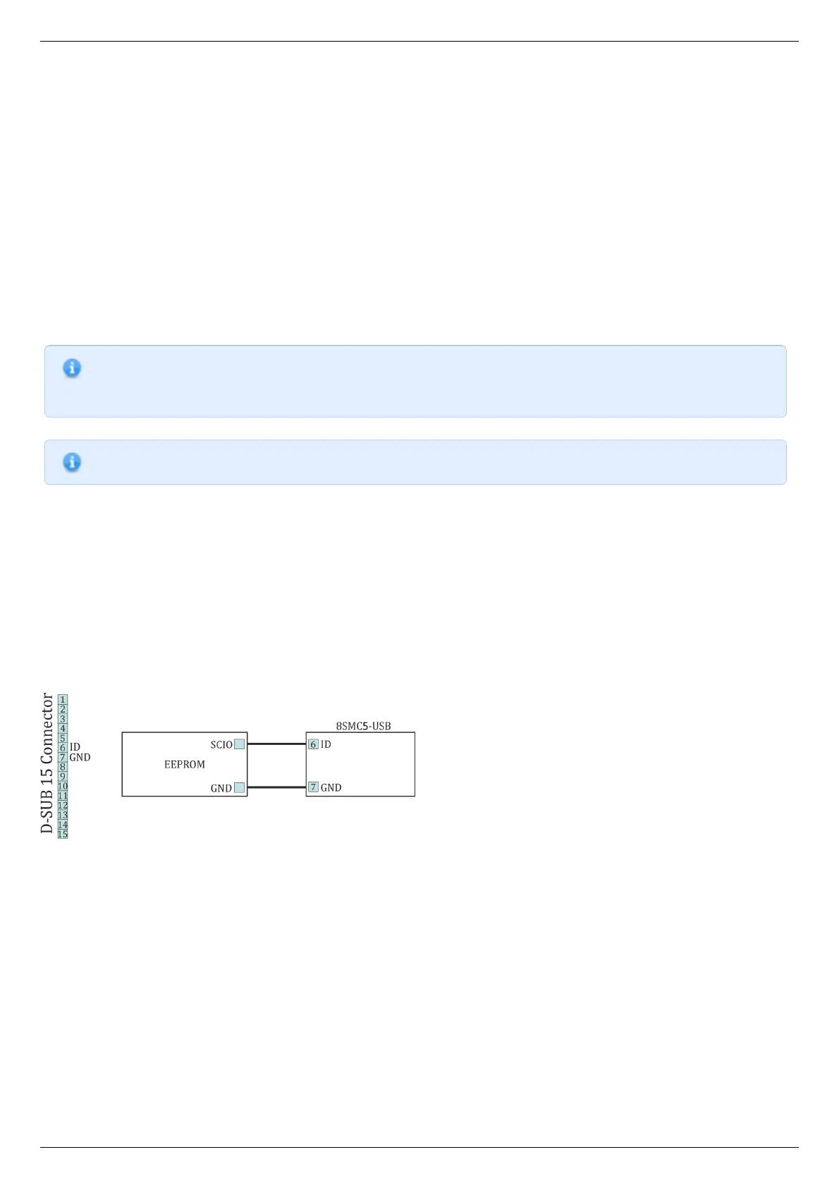
Connection diagram
Outputs for connection to the memory chip are located on the D-SUP 15 pin connector for all systems ( controller board, one-axis and
two-axis in box.
Connection diagram for external memory test